

Drill string tubular component
A tubular, component technology, applied in drill pipe, drill pipe, casing, etc., that can solve problems such as stopping the drilling process, slowing down, and hindering the movement of the drill string.
- Summary
- Abstract
- Description
- Claims
- Application Information
AI Technical Summary
Problems solved by technology
Method used
Image


Examples
Embodiment Construction
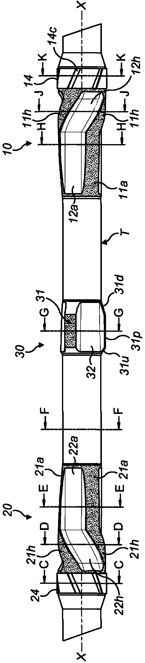
[0064] Referring now to the drawings, a drill string tubular member includes a base tube T having a downhole end and an uphole end (see figure 1 ), and at those ends, there are usually corresponding interface (box) and pin (pin) connectors for connecting to the drill string. Typically, the tubing is provided within the bottom hole assembly (BHA) adjacent the drill bit, and the tubing T may optionally be a heavyweight drill collar or heavyweight drill pipe known for these purposes. The interface and pin connectors at the ends of the tube T typically have an outer diameter that is larger than the nominal outer diameter of the tube T between the two ends. In the example shown, the nominal outer diameter of the central section of the tube T is typically 5-7 / 8". The tube T typically comprises 5-7 / 8" heavyweight drill pipe.
[0065] On the outer surface of the tube T there are usually three collars comprising radial protrusions. Said at least one first axial impeller is arranged o...
PUM
 Abstract
Description
Claims
Application Information