Sealing method and internal sealing device used for volatile matter main channel of tank furnace

A tank furnace and volatile content technology, which is applied to the sealing of the engine, engine components, mechanical equipment, etc., can solve the problems of furnace combustion out of control, fire, and heat loss and deformation of the insulation brick layer, so as to achieve long service life and ensure product quality and product performance, the effect of simple structure of the device

Active Publication Date: 2017-04-12
GUIYANG AL-MG DESIGN & RES INST
View PDF7 Cites 0 Cited by
  • Summary
  • Abstract
  • Description
  • Claims
  • Application Information

AI Technical Summary

Problems solved by technology

[0004] The purpose of the present invention is to provide a sealing method for the volatile matter main channel of the tank type furnace and the internal sealing device used to solve the problem of the different inside of the tank type furnace wall. The inconsistent thermal expansion rate of the refractory material layer leads to cracks between the layers, preventing air from entering the volatile main channel from the cracks and combusting with the volatiles, causing the top of the furnace to catch fire; or preventing the volatiles from flowing through these cracks under the negative pressure in the furnace. It enters the observation hole downwards and combusts with the air leaking in from the outside of the furnace, causing the insulation brick layer to be burned and deformed, and the furnace combustion is out of control

Method used


Image

  • Sealing method and internal sealing device used for volatile matter main channel of tank furnace
  • Sealing method and internal sealing device used for volatile matter main channel of tank furnace
  • Sealing method and internal sealing device used for volatile matter main channel of tank furnace

Examples


Embodiment Construction

[0022] The present invention will be further described in detail below in conjunction with the accompanying drawings and embodiments, but not as any limitation to the present invention.

[0023] Example.

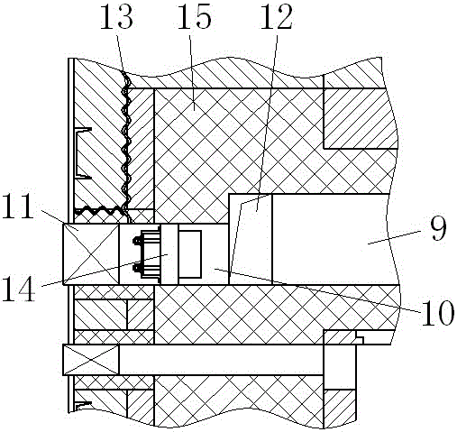
[0024] The sealing method of the volatile matter main channel of the tank furnace, such as figure 1 As shown, the wall of the retort furnace is composed of multiple layers of refractory material, the top of the retort furnace is provided with a volatile matter main channel 9, and the volatile matter main channel 9 is provided with a main channel cleaning hole across the entire retort furnace wall 10; The method is to add an inner sealing device 14 at the innermost refractory material layer 15 of the tank furnace wall at the cleaning hole 10 of the main road, which cuts off the channel between the outer furnace body crack 13 and the volatile part main road 9, Make the air infiltrated from the crack 13 and the volatile matter in the volatile matter main channel 9 unable to co...


PUM


Abstract

The invention discloses a method for sealing the main channel of volatile matter in a pot furnace and an internal sealing device used therefor. The wall body of the pot furnace targeted by the method is composed of multiple layers of refractory material layers, and the top of the pot furnace is provided with a volatile matter The main road, the main road of volatiles is equipped with a main road cleaning hole that goes over the entire tank furnace wall. An inner sealing device is added at the innermost refractory layer of the tank furnace wall at the main road cleaning hole to isolate the outer layer of the furnace. The passage between the cracks in the body and the main volatile channel prevents the air infiltrated from the cracks from combining with the volatiles in the main volatile channel. The invention perfectly solves the cracks between the layers caused by the inconsistency of the thermal expansion rates of different refractory material layers inside the tank furnace wall, so that the air enters the volatile matter main channel from the cracks and combusts with the volatile matter to cause the furnace top to catch fire. Or the volatile matter escapes downward from the crack into the observation hole under the negative pressure in the furnace, and burns together with the air leaking in from the outside of the furnace, causing the insulation brick layer to burn and deform, and the furnace burns out of control.

Description

technical field [0001] The invention relates to a method for sealing a volatile matter main channel of a tank type furnace and an inner sealing device used therefor, belonging to the technical field of sealing the volatile matter main channel of a tank type furnace. Background technique [0002] The volatile matter emitted in carbon production is a harmful combustible gas. In order to save energy and protect the environment, the current practice is to use the volatile matter in the tank furnace as an auxiliary fuel from the tank body to the fire channel for combustion. The volatile matter produced in the process of carbon production is collected by the volatile matter main channel on the top of the tank furnace, and the volatile matter in the volatile matter main channel is introduced downward into each layer of fire through the volatile matter branches arranged in the front and rear walls of the tank type furnace. Burning deep in the observation port. The main channel of v...

Claims


Application Information

Patent Timeline
Patent Type & Authority Patents(China)
IPC IPC(8): F16J15/00
Inventor 陈宁
Owner GUIYANG AL-MG DESIGN & RES INST
Why Eureka
Try Eureka