High Efficiency Burner Assembly

A burner and assembly technology, which is applied in the field of high-efficiency burner assemblies, can solve the problems of large gas power limitation and small scope of application, and achieve the effects of simple structure, wide application scope and high energy efficiency

Active Publication Date: 2016-01-27
广东年代集成厨电有限公司
View PDF8 Cites 0 Cited by
  • Summary
  • Abstract
  • Description
  • Claims
  • Application Information

AI Technical Summary

Problems solved by technology

But the fire distributor 3 can only divide the flame of the gas range into two layers, that is, a central flame layer formed by the fire distributor 3 and the air distribution pipe 2 positioned at the center, and a central flame layer formed by the fire distributor 3 and the air distribution pipe 2 positioned at the periphery. There is only one layer of peripheral flame layer, and the gas power of gas stoves with only two layers of flame is relatively limited. Therefore, the burner assembly is generally only suitable for small families and has a small scope of application.

Method used


Image

  • High Efficiency Burner Assembly
  • High Efficiency Burner Assembly
  • High Efficiency Burner Assembly

Examples


no. 1 example

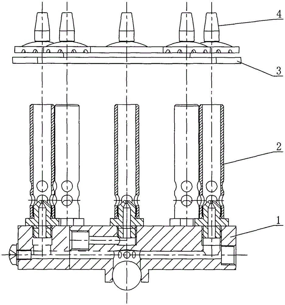
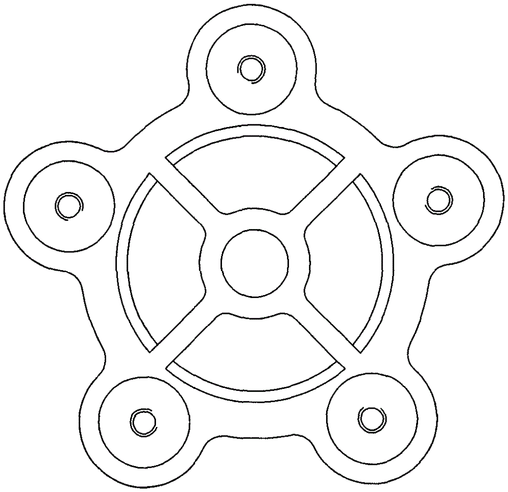
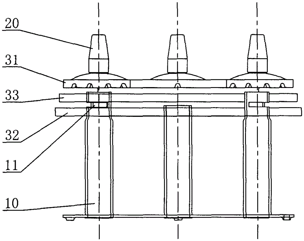
[0024] see Figure 3-Figure 4 , the high-efficiency burner assembly includes a fire distributor and a burner gas distribution seat (not shown in the figure) corresponding to the gas path of the fire distributor. A central flame layer is formed, and a central fire cover (not shown in the figure) can also be provided at the center of the fire distributor to meet the requirements of use. The fire distributor and the peripheral air duct 10 form a peripheral flame layer; the peripheral flame layer is at least divided into two layers , The fire distributor includes a fire distributor upper cover 31 and a fire distributor lower cover 32.

[0025] In this embodiment, the peripheral flame layer is divided into two layers, which are inner and outer layers. Wherein, the fire distributor also includes a fire distributor middle cover 33 arranged between the fire distributor upper cover 31 and the fire distributor lower cover 32, and the fire distributor upper cover 31 and the fire distrib...

no. 2 example

[0030] see Figure 5-Figure 6 , the main difference between the high-efficiency burner assembly and the first embodiment is that the upper cover 31 of the fire distributor and the lower cover 32 of the fire distributor are stacked in dislocation, that is, the inner and outer flames will be respectively equipped with air ducts 10 ( Peripheral airway tube 10 totally 8 groups), therefore, the airway tube 10 top that is positioned at periphery is open and can meet the requirement of supplying air (oxygen), simplifies the processing procedure of airway tube 10. In this embodiment, the two ends of the section of the fire distributor are stepped and gradually decrease from top to bottom, that is, the peripheral flame layer is layered up and down. Compared with the first embodiment, the combustion area of ​​this embodiment can be improved more effectively. Therefore, this embodiment is especially suitable for use in hotel kitchens (for large pots and stoves).

[0031] In addition, th...

no. 3 example

[0034] see Figure 7 , The main difference between the high-efficiency burner assembly and the second embodiment is that the two ends of the cross-section of the fire distributor are stepped from top to bottom and outwards, that is, the peripheral flame layer is layered inside and outside. This embodiment is particularly suitable for use at home (for small pots and stoves).

[0035] Other parts not described are the same as the second embodiment and will not be repeated.


PUM


Abstract

An efficient combustor assembly comprises a distributor and a furnace end gas distribution base corresponding to a gas circuit of the distributor. The distributor is connected with gas guide tubes. The distributor and the gas guide tube located at the center form a center flame layer. The distributor and the gas guide tubes located on the periphery form peripheral flame layers. The peripheral flame layers are divided into at least two layers. The distributor comprises an upper distributor cover and a lower distributor cover. The upper distributor cover and the lower distributor cover are repeatedly stacked up and down or are stacked in a staggered mode. The distributor further comprises a middle distributor cover. The upper distributor cover and the middle distributor cover form one peripheral flame layer, and the middle distributor cover and the lower distributor cover form the other peripheral flame layer, or the upper distributor cover forms one peripheral flame layer, and the middle distributor cover forms the other peripheral flame layer. By the adoption of the efficient combustor assembly, the combustion area of flames is increased, coverage blanks of flames are reduced or eliminated, the combustion power of the combustor assembly is greatly increased, heat efficiency is improved, the waste gas emission load is reduced, and the environment friendliness effects of saving energy and reducing emission are possessed.

Description

technical field [0001] The invention relates to a high-efficiency burner assembly. Background technique [0002] On June 6, 2007, I disclosed a burner assembly device of a gas stove in Chinese Patent Document No. CN1975261, including a burner head, and an outer jet pipe above the burner head, which is fixedly connected to the lower end of the outer jet pipe The fixed plate, the outer fire cover set on the upper port of the outer jet pipe, etc., is characterized in that: the burner is provided with an air inlet of the inner air chamber and an air outlet in the middle part connected with it, and an air inlet of the outer air chamber And the air outlet of the outer ring symmetrically arranged along the center that communicates with it, the inner nozzle pipe that is screwed and fixedly connected with it is set at the air outlet of the middle part and the outer ring; The upper port of the outer jet pipe is respectively provided with an inner fire cover and an integral outer fire...

Claims


Application Information

Patent Timeline
Patent Type & Authority Patents(China)
IPC IPC(8): F23D14/84
Inventor 刘洪凯
Owner 广东年代集成厨电有限公司
Why Eureka
Try Eureka