Fuel supporting plate for improving non-premixed combustion of RBCC (rocket-based combined cycle) bimodal combustion chamber

A combustion chamber and dual-mode technology, applied in the direction of combustion chamber, continuous combustion chamber, combustion method, etc., can solve the problems of incoming flow conditions and single fuel injection position, and achieve easy processing, strong turbulence, and compact structure simple effect

Inactive Publication Date: 2014-04-16
NORTHWESTERN POLYTECHNICAL UNIV
View PDF8 Cites 11 Cited by
  • Summary
  • Abstract
  • Description
  • Claims
  • Application Information

AI Technical Summary

Problems solved by technology

How to achieve efficient and stable combustion of fuel in a short combustion chamber has always been the core issue of the RBCC dual-mode combustion chamber. In the document AIAA2007-5404 "Pylon Fuel Injector Design for a Scramjet Combustor", it is mentioned that the plug-in wedge-shaped support plate is used for Fuel injection, and adding a staggered structure at the end of the support plate can enhance the mixing of fuel. The main technical principle is to use the low-velocity recirculation zone formed at the end of the support plate to provide sufficient mixing and reaction time for the fuel to meet self-sustained ignition In addition, the shear layer velocity gradient and turbulence intensity at the edge of the recirculation zone are large, which i...

Method used


Image

  • Fuel supporting plate for improving non-premixed combustion of RBCC (rocket-based combined cycle) bimodal combustion chamber
  • Fuel supporting plate for improving non-premixed combustion of RBCC (rocket-based combined cycle) bimodal combustion chamber
  • Fuel supporting plate for improving non-premixed combustion of RBCC (rocket-based combined cycle) bimodal combustion chamber

Examples


Embodiment Construction

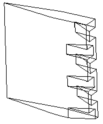
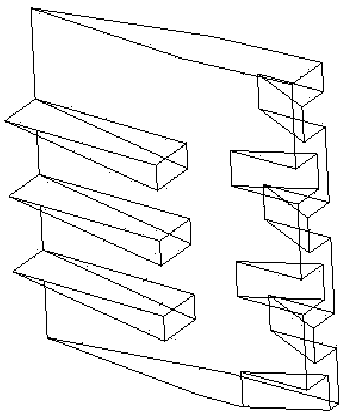
[0032] This embodiment is a fuel support plate for improving mixed combustion in an RBCC dual-mode combustor.

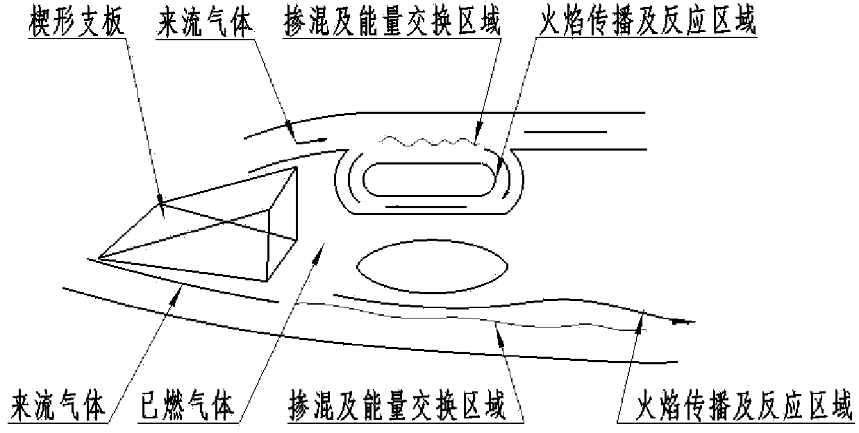
[0033] refer to Figure 1 to Figure 13 , the present invention is used to improve the fuel support plate of RBCC dual-mode combustor mixed combustion, is a kind of fuel support plate suitable for RBCC combustion organization under wide flow conditions, and is a flow direction vortex fuel support plate with a wedge-shaped protrusion on one side The structure of the fuel support plate includes the fuel support plate main body 1 and the fuel support plate injection block 2 .

[0034] The specific structure and assembly are as follows:

[0035] (1) The front body of the fuel support plate is a wedge-shaped structure with a wedge angle of 15°, and the rear body of the support plate is a straight section with a length of 25 mm and a thickness of 10 mm; three equally spaced wedge-shaped protrusions are evenly distributed on the outside of the fuel support plate in the vert...


PUM


Abstract

The invention discloses a fuel supporting plate for improving non-premixed combustion of a RBCC (rocket-based combined cycle) bimodal combustion chamber. The streamwise vortex fuel supporting plate is in a structure with unilateral wedged bosses, and two fuel supporting plate bodies are symmetrically distributed on two sides of a rocket. The front portion of the fuel supporting plate is wedged, the rear portion of the fuel supporting plate is straight, and three wedged bosses at equal intervals are arranged on the outer side of the front portion and fixedly connected with the supporting plate. The upper portion of a fuel jet block is provided with two screw holes connected with fuel jet hoses, fuel passage holes in the fuel jet block are communicated with the screw holes, and the lower portion of the fuel jet block is connected with a passage on the fuel supporting plate. The fuel jet block is fixed onto an engine, and jet positions can be changed in different experimental operating conditions. By means of the structure of the fuel supporting plate, guide vortexes of fluids on the lateral sides of the supporting plate can be intensified to enable fuel mixing to be more effective, a regular shear layer on the rear side of the supporting plate is reasonably destroyed to achieve higher turbulence level of the shear layer on the rear side of the supporting plate, the area of a combustion boundary layer is broadened, and the fuel can be better mixed with an incoming flow to form a larger combustion area.

Description

technical field [0001] The invention belongs to a fuel support plate structure for enhancing fuel mixing and diffusion, and in particular relates to a fuel support plate for improving the mixing combustion of an RBCC dual-mode combustion chamber. Background technique [0002] The rocket ramjet combined cycle (RBCC) engine organically combines the rocket engine and the ramjet engine in the same flow channel, so that it can enable the optimal working mode at different flight altitudes and Mach numbers, and give full play to the respective capabilities of the rocket engine and the ramjet engine. The characteristics of the RBCC engine not only have high specific impulse and high thrust-to-weight ratio, but also have the advantages of zero-speed start and reusability. How to achieve efficient and stable combustion of fuel in a short combustion chamber has always been the core issue of the RBCC dual-mode combustion chamber. In the document AIAA2007-5404 "Pylon Fuel Injector Design...

Claims


Application Information

Patent Timeline
IPC IPC(8): F23R3/28
Inventor 魏祥庚秦飞吕翔刘佩进何国强王亚军潘科玮
Owner NORTHWESTERN POLYTECHNICAL UNIV
Why Eureka
Try Eureka