Mirror-like surface testing method

A test method and surface test technology, applied in the field of measurement, can solve the problems of difficult processing, complex optical system, high manufacturing cost, etc., achieve good anti-noise performance, simplify the system structure, and reduce the effect of measurement cost

Active Publication Date: 2014-04-16
SHINING 3D TECH CO LTD
View PDF3 Cites 4 Cited by
  • Summary
  • Abstract
  • Description
  • Claims
  • Application Information

AI Technical Summary

Problems solved by technology

[0003] At present, it is very difficult to measure the mirror-like surface, especially the measurement of the depth-like mirror-like surface. The main reasons are: 1. The mirror-like surface does not have diffuse reflection characteristics, and the mature fringe projection profile cannot be used for the measurement of the mirror-like surface technology; 2. The existing mirror-like surface measurement requires a complex optical system, such as using computational holographic optical elements to compensate the wavefront. A specific example is that when measuring the surface of a parabolic mirror, a phase-shifting interferometer is generally used Auxiliary mirror complete
This method has high precision, but in the measurement process, an auxiliary mirror with the same size or larger size as the tested element is needed, and such a high-precision mirror is difficult to process and high in manufacturing cost

Method used


Image

  • Mirror-like surface testing method
  • Mirror-like surface testing method
  • Mirror-like surface testing method

Examples


Embodiment Construction

[0030] In order to make the object, technical solution and advantages of the present invention clearer, the present invention will be further described in detail below in conjunction with the accompanying drawings and embodiments. It should be understood that the specific embodiments described here are only used to explain the present invention, not to limit the present invention.

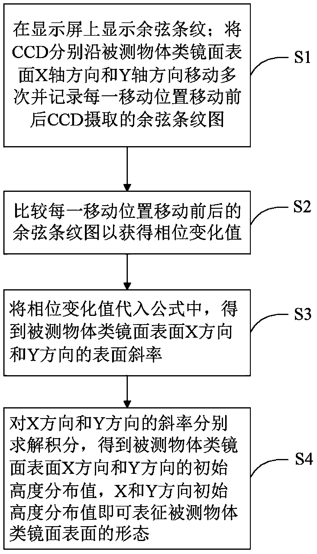
[0031] Please refer to figure 1 , figure 1 It is a flowchart of a method for testing mirror-like surfaces in a preferred embodiment of the present invention. figure 1 Among them, the mirror-like surface test method includes steps:

[0032] S1: Display cosine fringes on the display screen; move the CCD along the X-axis and Y-axis directions of the mirror-like surface of the measured object several times, and record the cosine fringe patterns captured by the CCD before and after each moving position.

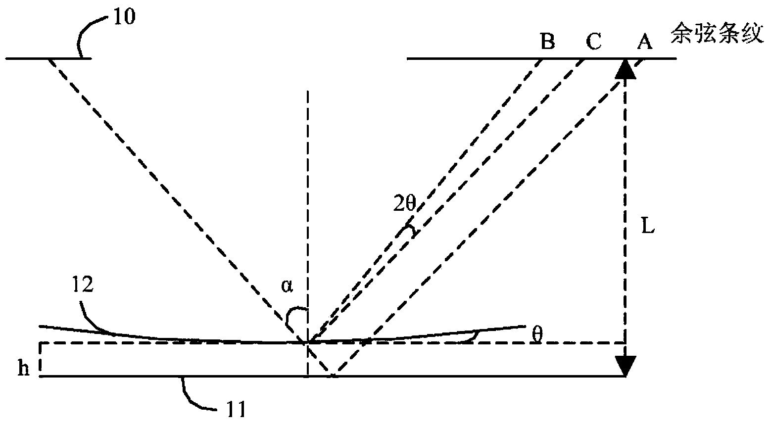
[0033] Since the surface of the object to be measured is a mirror-like surface, that is, it is n...


PUM


Abstract

The invention discloses a mirror-like surface testing method and belongs to the technical field of measurement. The mirror-like surface testing method solves the problem of high testing costs of existing mirror-like surface testing methods and comprises displaying cosine stripes on a display screen, moving a CCD (charge coupled device) in the X-axis direction and the Y-axis direction of the surface of an object to be tested to obtain the cosine stripe images of every moving position before and after the movement, which are shot by the CCD, comparing the cosine stripe images of every moving position before and after the movement to obtain phase change value, obtaining the surface slopes of the X-direction and the Y-direction of the mirror-like surface of the object to be tested through the phase change value and obtaining the initial height distribution value of the X-direction and the Y-direction of the mirror-like surface of the object to be tested by integral-solving the slopes. The mirror-like surface testing method does not require an auxiliary reflector or an interferometer, requires only one CCD camera during testing and does not require calibration of the CCD camera, thereby effectively reducing the testing cost and simplifying the system structure. The invention also provides a mirror-like surface testing device.

Description

technical field [0001] The invention relates to the field of measurement technology, in particular to a mirror-like three-dimensional curved surface testing method and device. Background technique [0002] Optical three-dimensional surface measurement technology has been widely used in high-speed inspection, product development, quality control, reverse engineering, CAD / CAM and other fields due to its advantages of high precision, high efficiency and non-contact. In engineering, especially in modern manufacturing, there are a large number of mirror-like objects that need to be measured, for example, aspheric mirrors in the automotive industry, car body surfaces after painting and waxing, polished mold surfaces, and ceramic tile surfaces in the architectural ceramics industry etc., the surfaces of these objects all have mirror-like reflective properties. [0003] At present, it is very difficult to measure the mirror-like surface, especially the measurement of the depth-like...

Claims


Application Information

Patent Timeline
Patent Type & Authority Applications(China)
IPC IPC(8): G01B11/24
Inventor 赵晓波王文斌
Owner SHINING 3D TECH CO LTD
Why Eureka
Try Eureka