A method and apparatus for measuring multimode perfect vortex beams

A vortex beam, perfect technology, applied in the field of optical measurement, can solve the problems of grating method crosstalk, difficult segmentation processing, etc., to achieve the effect of large dynamic range, convenient and flexible measurement, and simple structure

Active Publication Date: 2022-08-02
INST OF OPTICS & ELECTRONICS - CHINESE ACAD OF SCI
View PDF9 Cites 0 Cited by
  • Summary
  • Abstract
  • Description
  • Claims
  • Application Information

AI Technical Summary

Problems solved by technology

At present, the measurement range of the grating method is within ±20, and the grating method is easily affected by crosstalk
However, the square microlens array can only measure single-mode perfect vortex beams. For multi-mode perfect vortex beams, it is difficult to divide each mode by using square microlens arrays.

Method used


Image

  • A method and apparatus for measuring multimode perfect vortex beams
  • A method and apparatus for measuring multimode perfect vortex beams
  • A method and apparatus for measuring multimode perfect vortex beams

Examples


Embodiment 1

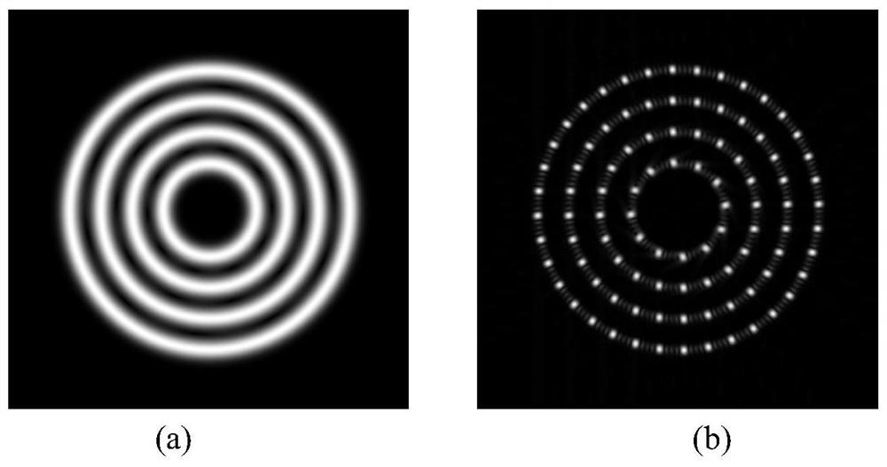
[0046] Example 1: A multimode perfect vortex beam composed of four modes, respectively l 1 =20,R 1 =0.6mm, l 2 =30,R 2 =1mm, l 3 =40,R 3 =1.4mm, l 4 =50,R 4 =1.8mm. like image 3 (a) shows the light field distribution of a multi-mode perfect vortex beam with four modes superimposed. After amplitude modulation, the four modes are arranged in concentric circles. image 3 (b) is the distribution of the spot array after passing through the fan-shaped microlens array, the generated multi-mode perfect vortex beam matches the fan-shaped microlens array, and each ring of the fan-shaped microlens array carries a perfect vortex beam pattern, Therefore, each mode can be well separated. right image 3 (b) Perform processing, scan the light spot information on each ring from the center, and determine the closed curve, and then calculate the phase slope information of the position of the light spot on each ring. According to formula (1), the size and symbol. The result is as F...


PUM


Abstract

The invention discloses a method and a device for measuring a multi-mode perfect vortex beam. The invention utilizes a fan-shaped microlens array arranged in an annular shape to segment the information of each ring of a multi-mode perfect vortex beam, and solves the size and sign of each mode through closed curve integration. After the multi-mode perfect vortex beam is incident on the fan-shaped microlens array, a circularly distributed light spot array is obtained on the focal plane, and then the circular scanning starts from the center of the light spot array. The phase slope is finally brought into the closed curve integration to get the result. The method is easier to classify and process data, and can measure a wider range of modes; the method is simple in structure, convenient and fast in measurement, and has great application prospects in the fields of free-space optical communication, optical fiber communication, and optical tweezers technology.

Description

technical field [0001] The invention belongs to the field of optical measurement, and specifically relates to a method for measuring the size and sign of each mode of a multimode perfect vortex beam. Background technique [0002] The angular momentum of light is divided into spin angular momentum and orbital angular momentum. Among them, the spin angular momentum is reflected in the polarization of light, which has long been known to people, while the orbital angular momentum of light was only confirmed by Allen et al. in 1992. Phase term The beam has The magnitude of the orbital angular momentum (OAM), where l is called the topological charge or mode number. This type of beam is also called a vortex beam, its phase surface is a helical structure, the center is a phase singularity, and the light intensity is annular distribution. The ring radius of a conventional vortex beam is the same as Proportional, not very convenient when applied in multiple modes. In 2013, per...

Claims


Application Information

Patent Timeline
Patent Type & Authority Patents(China)
IPC IPC(8): G01J9/00G01J9/02G01J1/42G02B27/09
CPCG01J9/00G01J9/02G01J1/4257G02B27/0961G01J2009/002
Inventor 沈锋唐奥兰斌张利宏
Owner INST OF OPTICS & ELECTRONICS - CHINESE ACAD OF SCI
Why Eureka
Try Eureka