Movement vision measurement method of rocket engine nozzle and high-brightness infrared light-emitting device used in method

A rocket engine and infrared light-emitting technology, which is applied in measuring devices, photogrammetry/video metrology, surveying and navigation, etc., can solve the problem that the camera image plane cannot correctly identify cooperation targets, etc., and achieve simple structure and improved accuracy , The effect of clear collection

Active Publication Date: 2014-04-16
HARBIN INST OF TECH
View PDF4 Cites 1 Cited by
  • Summary
  • Abstract
  • Description
  • Claims
  • Application Information

AI Technical Summary

Problems solved by technology

[0003] In order to solve the problem that the cooperation target cannot be correctly identified on the camera image plane due to the huge difference between the hot and cold test run process of the nozzle and the working conditions of the simulated nozzle when measuring the motion parameters of the nozzle of the rocket engine, the present invention proposes A visual measurement method for rocket engine nozzle motion and a high-brightness infrared light-emitting device used in the method

Method used


Image

  • Movement vision measurement method of rocket engine nozzle and high-brightness infrared light-emitting device used in method
  • Movement vision measurement method of rocket engine nozzle and high-brightness infrared light-emitting device used in method
  • Movement vision measurement method of rocket engine nozzle and high-brightness infrared light-emitting device used in method

Examples


specific Embodiment approach 1

[0021] The specific embodiment one, a kind of rocket engine nozzle movement visual measurement method described in this specific embodiment, it comprises the following steps:

[0022] Step 1. Arrange multiple infrared light-emitting points on the outer surface of the rocket engine nozzle, and connect the infrared light-emitting points in parallel with multiple channels to form a light-emitting circuit. Each channel is composed of two infrared light-emitting points and an adjustable voltage divider resistor. In a series structure, the number of the channels is 2 or 3, and the infrared light-emitting point is realized by a high-brightness infrared light-emitting device,

[0023] Step 2, setting an infrared filter before the lens of the image acquisition device,

[0024] Step 3, connect the image acquisition signal output end of the image acquisition device with the image acquisition signal input end of the visual measurement system control computer,

[0025] Step 4. Aim the len...

specific Embodiment approach 2

[0029] Specific embodiment two, combine Figure 7 Describe this specific embodiment, the difference between this specific embodiment and the visual measurement method of a rocket engine nozzle movement described in specific embodiment 1 is that the light-emitting circuit described in step 1 also includes a power supply VCC, a switch S1 and a circuit pass. The off indicator LED1, the power supply VCC is used to supply power to the light-emitting circuit, the switch S1 is used to control the on or off of the light-emitting circuit, the circuit on-off indicator LED1 is connected in series with the switch S1, and is used to display the on or off of the light-emitting circuit status.

specific Embodiment approach 3

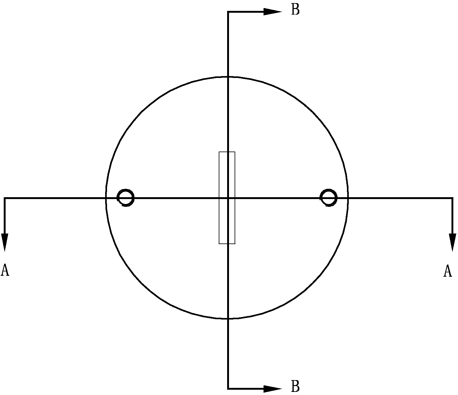
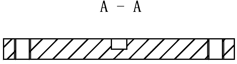
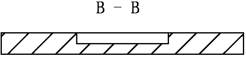
[0030] Specific embodiment three, combine Figure 1 to Figure 6 Illustrate this specific embodiment, the high-brightness infrared light-emitting device used in a kind of rocket engine nozzle motion visual measurement method described in specific embodiment 1 comprises an infrared light-emitting circuit board, an infrared light-emitting diode and a housing, and the infrared light-emitting diode is fixed on On the infrared light-emitting circuit board, the infrared light-emitting diode includes 9 infrared light-emitting cores working in parallel. Both sides of the infrared light-emitting circuit board are processed with symmetrical light holes. The shell includes a shell and a base. The shell is cylindrical structure, the infrared light-emitting circuit board is fixed in the casing, and a through hole is opened in the center of the upper surface of the casing. The positive and negative wires of the infrared light-emitting diode are connected to the external power supply through ...


PUM

PropertyMeasurementUnit
Outer diameteraaaaaaaaaa
The inside diameter ofaaaaaaaaaa
Outer diameteraaaaaaaaaa

Abstract

The invention discloses a movement vision measurement method of a rocket engine nozzle and a high-brightness infrared light-emitting device used in the method, relates to the field of movement vision measurement of the rocket engine nozzle, and solves the problems that a cooperative target cannot be correctly identified on a camera image plane caused by a great difference between a cold and hot commissioning process of the nozzle and a simulated nozzle working condition in measurement on movement parameters of the rocket engine nozzle. A plurality of infrared luminous points are arranged on the outer surface of the rocket engine nozzle and connected to form a light-emitting circuit in a multi-channel parallel manner; image collection equipment collects the images of a plurality of infrared luminous points at the outer surface of the rocket engine nozzle in movement and transmits the collected image to a vision measurement system control computer, so as to achieve the target of movement vision measurement of the rocket engine nozzle; the infrared luminous points are achieved by adopting the high-brightness infrared light-emitting device. The movement vision measurement method is applicable to movement vision measurement of the rocket engine nozzle.

Description

technical field [0001] The invention relates to the field of visual measurement of rocket engine nozzle movement, in particular to the field of infrared light emitting devices in the visual measurement of rocket engine nozzle movement. Background technique [0002] The measurement of motion parameters (such as swing center and swing angle) of rocket engine nozzle is an important quality assurance for the attitude and trajectory control, range and landing accuracy of rockets and missiles. During the cold and hot test run of the existing rocket engine, the method adopted is to measure the angular displacement of the motion servo control rod with a rotary potentiometer, and then obtain the motion parameters of the nozzle through geometric conversion. This is an indirect measurement, and there is still a large measurement error. At present, the visual method of the cooperative target can realize the measurement of the motion parameters of the simulated nozzle. The cooperative t...

Claims


Application Information

Patent Timeline
IPC IPC(8): G01C11/00
CPCG01C11/00
Inventor 郭玉波叶东于潇宇陈刚马惠萍
Owner HARBIN INST OF TECH
Why Eureka
Try Eureka