High-speed engraving and milling electric spindle

An electric spindle, engraving and milling technology, applied in the directions of large fixed members, maintenance and safety accessories, drive devices, etc., can solve the problems of small power and output torque, small motor, etc., to achieve increased power, superior operating performance, and less quantity Effect

Inactive Publication Date: 2014-04-23
GUANGZHOU HAOZHI ELECTROMECHANICAL
View PDF6 Cites 6 Cited by
  • Summary
  • Abstract
  • Description
  • Claims
  • Application Information

AI Technical Summary

Problems solved by technology

However, due to the limitation of the spindle volume, the built-in motor is generally smaller, and its power and output torque are smaller than traditional mechanical spindles.

Method used


Image

  • High-speed engraving and milling electric spindle

Examples


Embodiment Construction

[0021] Below, in conjunction with accompanying drawing and specific embodiment, the present invention is described further:

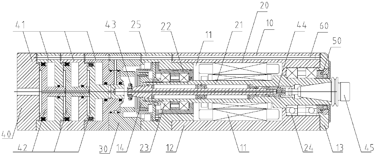
[0022] Please see figure 1 , a high-speed engraving and milling electric spindle of the present invention, which includes a body 10 with an inner cavity 11, a shaft system 20 arranged in the body 10, an aluminum water jacket 30, a broach system 40, an air seal system 50, and a water cooling system 60 and a drive motor (not shown). One end of the body 10 is provided with a lower cover 13 .

[0023] The rotating shaft system 20 includes a shaft core 21 , a bearing housing 22 , a first bearing 23 , a second bearing 24 and a housing housing 25 . The shaft core 21 is axially disposed in the inner cavity 11 of the machine body 10 . The first bearing 23 and the second bearing 24 are disposed at opposite ends of the shaft core 21 along the extending direction of the shaft core 21 for supporting the shaft core 21 . Wherein, the first bearing 23 is installed ...


PUM


Abstract

The invention relates to a high-speed engraving and milling electric spindle. The high-speed engraving and milling electric spindle comprises an engine body with an inner cavity, and a rotating shaft system, an aluminum water jacket, a broach system, an air sealing system, a water cooling system and a driving motor which are arranged inside the engine body, wherein a pull rod is penetrated inside a central spindle, and one end of the pull rod is penetrated inside the aluminum water jacket and opposite to a piston; a pulling claw assembly is arranged at one end, far away from the piston, of the pull rod and used for clamping a knife handle; the air sealing system comprises through grooves formed in the aluminum water jacket, a bearing seat outer sleeve and the engine body; the air sealing system comprises cooling water holes formed in an air cylinder, the aluminum water jacket, the bearing seat outer sleeve and the engine body. Compared with the prior art, the high-speed engraving and milling electric spindle disclosed by the invention is cylindrical, and the outer diameters of the engine body, the bearing seat outer sleeve, the aluminum water jacket and the air cylinder are basically the same. Meanwhile, the total length ratio of the engine body, the bearing seat outer sleeve, the aluminum water jacket and the air cylinder is 1: 1, so that the high-speed engraving and milling electric spindle is more balanced in the aspect of structural arrangement.

Description

[0001] technical field [0002] The invention relates to a high-speed engraving and milling electric spindle. [0003] Background technique [0004] The electric spindle is also called the motor built-in spindle, which is directly driven by the internal motor, instead of requiring an external servo motor to work like the traditional mechanical spindle. The electric spindle has a compact structure, so it can achieve high speed, high precision and high running stability. However, due to the limitation of the volume of the spindle, the built-in motor is generally smaller, and its power and output torque are smaller than those of traditional mechanical spindles. [0005] Contents of the invention [0006] Aiming at the deficiencies of the prior art, the object of the present invention is to provide a high-speed engraving and milling electric spindle with stable operation, high rotation speed and large torque. [0007] To achieve the above object, the present invention adop...

Claims


Application Information

Patent Timeline
Patent Type & Authority Applications(China)
IPC IPC(8): B23B19/02B23Q5/10
CPCB23Q5/10B23B31/265B23Q1/70B23Q11/127
Inventor 汤秀清
Owner GUANGZHOU HAOZHI ELECTROMECHANICAL
Why Eureka
Try Eureka