Edge-milling machine

An edge milling machine and frame technology, applied in milling machine equipment, milling machine equipment details, metal processing and other directions, can solve the problems of inability to guarantee plates, metal strips, affecting processing quality, etc., to achieve simple structure, ensure processing quality, and easy to use. Effect

Inactive Publication Date: 2014-04-23
宋芬
View PDF6 Cites 1 Cited by
  • Summary
  • Abstract
  • Description
  • Claims
  • Application Information

AI Technical Summary

Problems solved by technology

In order to improve the processing accuracy of the equipment, it is first necessary to ensure that the direction of advancement of the plate and metal strip cannot be changed. However, in the actual production process, it cannot be guaranteed that the plate and metal strip will always advance against the milling cutter, which will affect the processing quality.

Method used


Image

  • Edge-milling machine
  • Edge-milling machine
  • Edge-milling machine

Examples


Embodiment 1

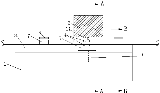
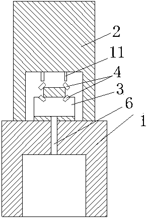
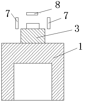
[0017] As shown in the figure, the edge milling machine of the present invention includes a base 1, a frame 2 is arranged on the base 1, a transmission channel 3 is arranged on the base 1, and the transmission channel 3 is located at the Below the frame 2, milling cutters 4 are respectively installed at the four corners of the workpiece on the frame 2. The position of the milling cutters 4 is adjustable, and the four milling cutters are located in the middle of the transmission channel 3. 4 is provided with a groove 5, a chip removal channel 6 is provided at the bottom of the groove 5, and guide devices are respectively provided on the base of the feed side and the discharge side of the frame 2, each Each of the guiding devices is located above the conveying channel 3, wherein the guiding device includes pressing plates 7 arranged on both sides of the workpiece, the distance between the two pressing plates 7 is adjustable, and an upper pressing plate 8 is also arranged above th...

Embodiment 2

[0019] As shown in the figure, the edge milling machine of the present invention includes a base 1, a frame 2 is arranged on the base 1, a transmission channel 3 is arranged on the base 1, and the transmission channel 3 is located at the Below the frame 2, milling cutters 4 are respectively installed at the four corners of the workpiece on the frame 2. The position of the milling cutters 4 is adjustable, and the four milling cutters are located in the middle of the transmission channel 3. 4 is provided with a groove 5, a chip removal channel 6 is provided at the bottom of the groove 5, and guide devices are respectively provided on the base of the feed side and the discharge side of the frame 2, each The two guiding devices are all located above the conveying channel 3, wherein the guiding device is provided with a baffle plate 9 on one side of the conveying channel 3, and a horizontally placed L-shaped pressing plate is arranged on the opposite side of the baffle plate 9. 10....


PUM


Abstract

The invention discloses an edge-milling machine which comprises a pedestal; a frame is disposed on the pedestal; a transfer channel is disposed on the pedestal; the transfer channel is located below the frame; milling cutters are mounted at positions corresponding to four corners of a workpiece on the frame; the positions of the milling cutters are adjustable; grooves are disposed at the positions corresponding to the four milling cutters in the transfer channel; a chip-discharging channel is disposed at the bottom of the grooves; guiding devices are respectively disposed at the charging side and the discharging side of the frame on the pedestal; each guiding device is located above the transfer channel. The edge-milling machine of the invention is good in milling effect, high in efficiency, fluent in process, not liable to trimming, suitable for metal bands with different widths and thicknesses, wide in application range, convenient and practical.

Description

technical field [0001] The invention relates to the technical field of metal processing, in particular to an edge milling machine for metal strip processing. Background technique [0002] The edge milling machine is mainly used for grinding the edges and corners of plates, metal strips, etc., and is more and more widely used because of its good grinding effect. Edge milling machine is a commonly used processing equipment for plates and metal strips. As customers gradually increase the quality requirements for finished products such as plates and metal strips, the processing accuracy of the equipment is also required to be higher and higher. In order to improve the machining accuracy of the equipment, it is first necessary to ensure that the forward direction of the plates and metal strips cannot be changed. However, in the actual production process, it is impossible to ensure that the plates and metal strips are always advancing against the milling cutter, which affec...

Claims


Application Information

Patent Timeline
Patent Type & Authority Applications(China)
IPC IPC(8): B23C3/12B23Q7/00
Inventor 宋芬
Owner 宋芬
Why Eureka
Try Eureka