Device and method for welding bourdon tube for pressure gauge

A welding device and welding method technology are applied in the field of Bourdon tube welding devices for pressure gauges, which can solve the problems of pits at the welding position, low service life, and easy corrosion of the welding seam, and achieve slow local flow rate, long service life, The effect of less weld defects

Active Publication Date: 2014-04-23
MAANSHAN NAITE INSTR TECH
View PDF10 Cites 4 Cited by
  • Summary
  • Abstract
  • Description
  • Claims
  • Application Information

AI Technical Summary

Problems solved by technology

[0007] Aiming at the problems in the prior art of welding the Bourdon tube of the pressure gauge that the through hole is easy to block, there are pits at the welding place, the weld seam is easy to corrode, and the service life is low, the invention provides a Bourdon tube welding device for a pressure gauge and Its welding method, the device can ventilate during welding to prevent the through hole from being blocked. At the same time, it is equipped with a water spray pipe to facilitate the cooling of the weld seam, and adding special substances in the water can play an anti-corrosion effect.

Method used


Image

  • Device and method for welding bourdon tube for pressure gauge
  • Device and method for welding bourdon tube for pressure gauge

Examples


Embodiment 1

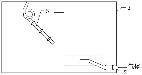
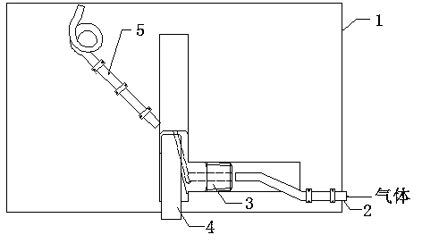
[0035]A Bourdon tube welding device for a pressure gauge, comprising a base 1, a vent pipe 2, a water spray pipe 5, a first groove and a second groove; the first groove and the second groove are arranged on the base 1; the One end of the second groove is vertically connected to the first groove; the air pipe 2 is fixed on the base 1, and one end of the air pipe 2 is arranged in the second groove; the water spray pipe 5 is arranged on the base 1. The cross section of the second groove is semicircular, the inner diameter of the second groove is equal to 2 cm, and the diameter d (inner diameter) of the air pipe 2 is equal to 1 cm. The axial centerline of the water spray pipe 5 and the axial centerline of the second groove (the cross section of the second groove is a semicircle, and the centers of all semicircles are connected into a line, which is the second groove The included angle of the axial centerline of ) is 135°. The port of the air pipe 2 is provided with a protrusion w...

Embodiment 2

[0043] Same as Example 1, the difference is that the inner diameter of the second groove is equal to 2.4 cm, the diameter d (inner diameter) of the air pipe 2 is equal to 0.8 cm, and the angle between the central axis of the air pipe 2 and the central axis of the second groove is 15°, and the gas introduced in step (2) is carbon dioxide. The welded Bourdon tubes had no clogging, and out of 1000 welded products, only 3 were unqualified. And the welding defects are significantly reduced by 70% compared with the welding defects when there is no ventilation. In particular, there is no depression or incomplete penetration of the welds inside the through holes, and the welded Bourdon tubes have not been corroded after one year of use.

Embodiment 3

[0045] Same as Example 1, the difference is that the inner diameter of the second groove is equal to 2.4 cm, the diameter d (inner diameter) of the air pipe 2 is equal to 1.2 cm, and the angle between the central axis of the air pipe 2 and the central axis of the second groove is 15°. The welded Bourdon tubes had no clogging, and out of 1000 welded products, only 3 were unqualified. And the welding defects are significantly reduced by 70% compared with the welding defects when there is no ventilation. In particular, there is no depression or incomplete penetration of the welds inside the through holes, and the welded Bourdon tubes have not been corroded after one year of use.


PUM


Abstract

The invention discloses a device and a method for welding a bourdon tube for a pressure gauge, and belongs to the field of pressure gauge production. The device comprises a base, a gas feeding tube, a water ejection tube, a first groove and a second groove, wherein the first groove and the second groove are formed in the base; one end of the second groove is vertically connected with the first groove; the gas feeding tube is fixed on the base; one end of the gas feeding tube is arranged in the second groove; the water ejection tube is arranged on the base. By the adoption of the device, a gas can be supplied in welding, so that through holes are prevented from being blocked, and meanwhile due to arrangement of the water ejection tube, weld seams can be conveniently cooled down, and meanwhile due to addition of special substances in water in the welding method, the anticorrosion effect can be achieved, and the welding defects can be greatly reduced.

Description

technical field [0001] The invention belongs to the field of pressure gauge production, and more specifically relates to a Bourdon tube welding device for pressure gauges and a welding method thereof. Background technique [0002] A pressure gauge refers to an instrument that uses elastic elements as sensitive elements to measure and indicate pressure higher than the environment. The application of pressure gauges is extremely common, and it pervades almost all industrial processes and scientific research fields. It can be seen everywhere in heat pipe network, oil and gas transmission, water and gas supply system, vehicle maintenance and other fields. Especially in the process of industrial process control and technical measurement, due to the high mechanical strength and convenient production of the elastic sensitive components of mechanical pressure gauges, mechanical pressure gauges are more and more widely used. In order to prevent shock and stability, the current pres...

Claims


Application Information

Patent Timeline
Patent Type & Authority Applications(China)
IPC IPC(8): B23K37/00B23K37/04
CPCB23K37/00B23K37/003B23K37/0426B23K2101/06
Inventor 束高祥高孝友
Owner MAANSHAN NAITE INSTR TECH
Why Eureka
Try Eureka