Electrically-controlled hydraulic or pneumatic kinetic energy recovering and releasing device

An electronically controlled hydraulic and kinetic energy recovery technology, which is applied in the direction of fluid pressure actuators, brake transmission devices, fluid pressure actuator system components, etc., can solve problems such as mechanical failure, personal safety issues, and loss of braking ability, and achieve Improve transportation capacity and production efficiency, improve energy utilization, and reduce energy loss

Inactive Publication Date: 2014-04-23
鞠锋
View PDF4 Cites 1 Cited by
  • Summary
  • Abstract
  • Description
  • Claims
  • Application Information

AI Technical Summary

Problems solved by technology

[0002] Now some vehicles, motors and some complex moving machinery are mostly braked by mechanical friction braking, that is, their kinetic energy is converted into heat energy through friction between objects and then disappears, so that kinetic energy is wasted during braking. Moreover, the large amount of heat energy easily transformed into by long-term friction will also increase the temperature of the brake, which will affect the braking effect of the brake, and even make it more likely to lose the braking ability, thereby causing mechanical failure and personal safety. Problem; there are still some motor brakes that use the method of supplying DC power to the motor to slow down or stop it. This will not only increase the DC equipment, but also waste some electric energy; moreover, most of the existing friction plates contain metal in the composition Elements, such as copper and iron, cannot be recycled and reused after being worn out, and the worn-out substances also pollute the environment. The high temperature caused by braking can easily cause vehicle tires to blow out, thus causing traffic accidents

Method used


Image

  • Electrically-controlled hydraulic or pneumatic kinetic energy recovering and releasing device
  • Electrically-controlled hydraulic or pneumatic kinetic energy recovering and releasing device

Examples


Embodiment 1

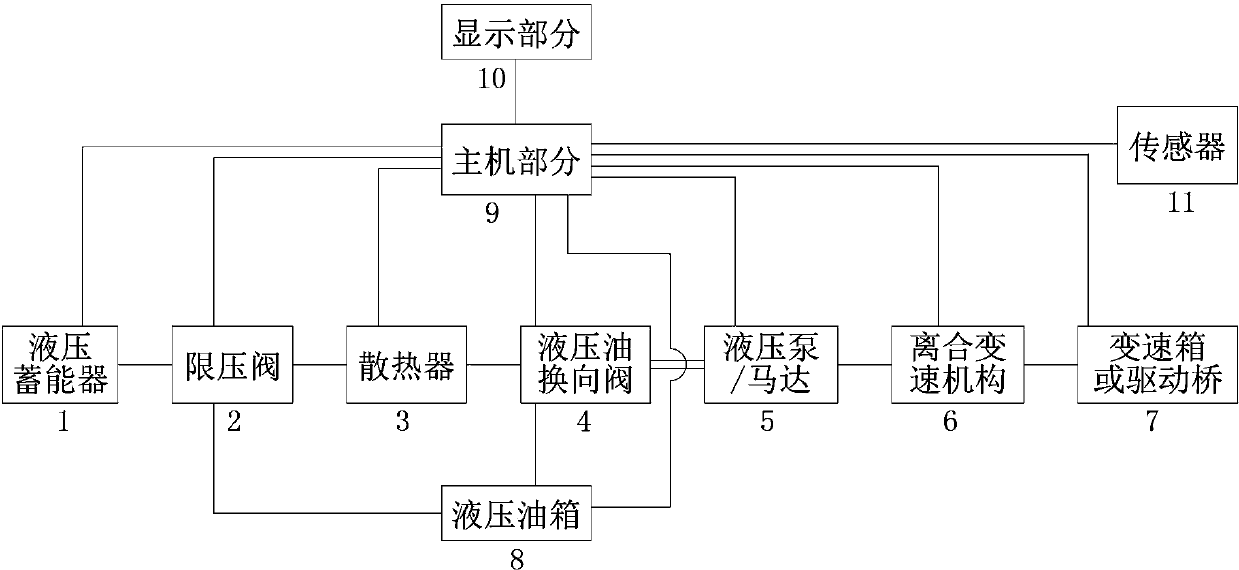
[0036] Embodiment 1: see figure 1 , the electronically controlled hydraulic or pneumatic kinetic energy recovery and release device of the present invention includes a hydraulic accumulator 1, a pressure limiting valve 2, a radiator 3, a reversing valve 4, a hydraulic pump / motor 5, a clutch transmission mechanism 6, and a gearbox Or drive axle 7, hydraulic oil tank 8, electronic control unit, sensor 11, one end of the clutch transmission mechanism 6 is connected with the gearbox or drive axle 7, and the other end is connected with the power shaft of the hydraulic pump / motor 5, and the hydraulic accumulator Energy device 1, pressure limiting valve 2, radiator 3, reversing valve 4, hydraulic oil tank 8 and hydraulic pump / motor 5 are connected through pipelines, and the electronic control unit includes a host part 9 and a display part 10, and the host part 9 and the display part 10 are connected by wires, and the display part 10 displays the working state of the system and perfor...

Embodiment 2

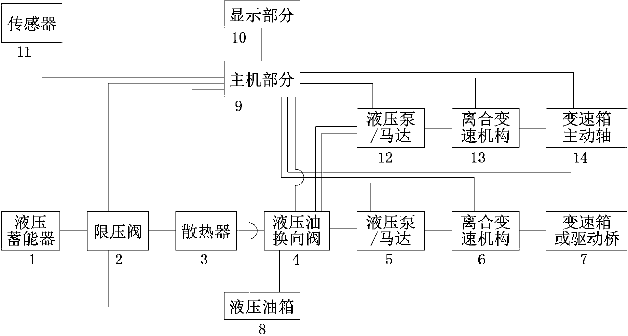
[0051] Example 2: see figure 2 , the electronically controlled hydraulic or pneumatic kinetic energy recovery and release device of the present invention includes a hydraulic accumulator 1, a pressure limiting valve 2, a radiator 3, a reversing valve 4, a hydraulic pump / motor 5, a clutch transmission mechanism 6, and a gearbox Or drive axle 7, hydraulic oil tank 8, electronic control unit, sensor 11, hydraulic pump / motor 12, clutch transmission mechanism 13, gearbox power shaft 14, described clutch transmission mechanism 6 one end is connected with gearbox or drive axle 7, The other end is connected with the power shaft of the hydraulic pump / motor 5, and the hydraulic accumulator 1, the pressure limiting valve 2, the radiator 3, the reversing valve 4, the hydraulic oil tank 8 are connected with the hydraulic pump / motor 5 through pipelines, and the The electric control unit includes a host part 9 and a display part 10, the host part 9 and the display part 10 are connected by a...


PUM


Abstract

The invention discloses an electrically-controlled hydraulic or pneumatic kinetic energy recovering and releasing device. The electrically-controlled hydraulic or pneumatic kinetic energy recovering and releasing device comprises a hydraulic accumulator, a pressure limiting valve, a radiator, a reversing valve, a hydraulic pump/motor, a clutch speed change mechanism, a transmission or driving axle, a hydraulic oil tank, an electric control unit and a sensor, wherein one end of the clutch speed change mechanism is connected with the transmission or driving axle, and the other end of the clutch speed change mechanism is connected with a power shaft of the hydraulic pump/motor; the hydraulic accumulator, the pressure limiting valve, the radiator, the reversing valve, the hydraulic oil tank and the hydraulic pump/motor are connected through a pipeline; the electric control unit is connected with the sensor, a controller portion on the hydraulic pump/motor and a controller portion on the reversing valve through leads. The kinetic energy of a moving object is transformed into molecular potential energy for storage by using a hydraulic accumulating or pneumatic accumulating method, and the stored molecular potential energy is transformed into the kinetic energy of the moving object when the object moves once again or accelerates, thereby fulfilling the aims of recycling, lowering the energy consumption and increasing the energy utilization ratio.

Description

technical field [0001] The invention relates to the field of energy recovery and utilization, in particular to an electronically controlled hydraulic or pneumatic kinetic energy recovery and release device. Background technique [0002] Now some vehicles, motors and some complex moving machinery are mostly braked by mechanical friction braking, that is, their kinetic energy is converted into heat energy through friction between objects and then disappears, so that kinetic energy is wasted during braking. Moreover, the large amount of heat energy easily transformed into by long-term friction will also increase the temperature of the brake, which will affect the braking effect of the brake, and even make it more likely to lose the braking ability, thereby causing mechanical failure and personal safety. Problem; there are still some motor brakes that use the method of supplying DC power to the motor to slow down or stop it. This will not only increase the DC equipment, but also...

Claims


Application Information

Patent Timeline
Patent Type & Authority Applications(China)
IPC IPC(8): F15B21/14B60T13/10
CPCB60T1/10
Inventor 鞠锋
Owner 鞠锋
Why Eureka
Try Eureka