
Quick-valve magnetic control gravity emergency drive device

A driving device and fast technology, applied in the direction of valve device, valve operation/release device, valve details, etc., can solve the problems of crude oil leakage, high maintenance cost, heavy casualties, etc., to eliminate process overpressure and realize automatic The effect of regulation

Inactive Publication Date: 2014-04-23
天津市塘沽津滨阀门有限公司
View PDF6 Cites 8 Cited by
  • Summary
  • Abstract
  • Description
  • Claims
  • Application Information

AI Technical Summary

Problems solved by technology

Numerous production practices and accident cases prove that there are defects and obvious hidden dangers in the control of existing pipeline process valves. The requirements for mechanical transmission are high, the failure rate is high, the maintenance cost is high, the support cost is high, and the dependence on mains power is high. At the same time, its own Hidden dangers also bring new safety issues to process control, especially in dangerous areas such as field and fire, and it is difficult to guarantee the reliability of automation functions
In the 7.16 accident of PetroChina in 2010, the crude oil pipeline of the oil depot in the Dalian Free Trade Zone exploded and caught fire. The crude oil leaked due to the inability to close the process after the electric gate was powered off. Combustion occurred; Qingdao Huangdao 11.22 Sinopec Crude Oil Pipeline Leakage Explosion Accident in 2013 caused heavy casualties and huge impact, also due to lack of timely detection and lack of effective means to automatically control process pressure and medium flow in emergencies
[0003] The inventor believes that the key to the occurrence of this major accident is the lack of automatic flow control devices for emergencies in the installation of crude oil pipelines, and the lack of automatic professional preventive equipment for emergency avoidance in the design.

Method used


Image

  • Quick-valve magnetic control gravity emergency drive device
  • Quick-valve magnetic control gravity emergency drive device
  • Quick-valve magnetic control gravity emergency drive device

Examples


Embodiment Construction

[0024] In order to make the present invention easier to understand, the technical solutions of the present invention will be described in detail below in conjunction with the accompanying drawings and embodiments.

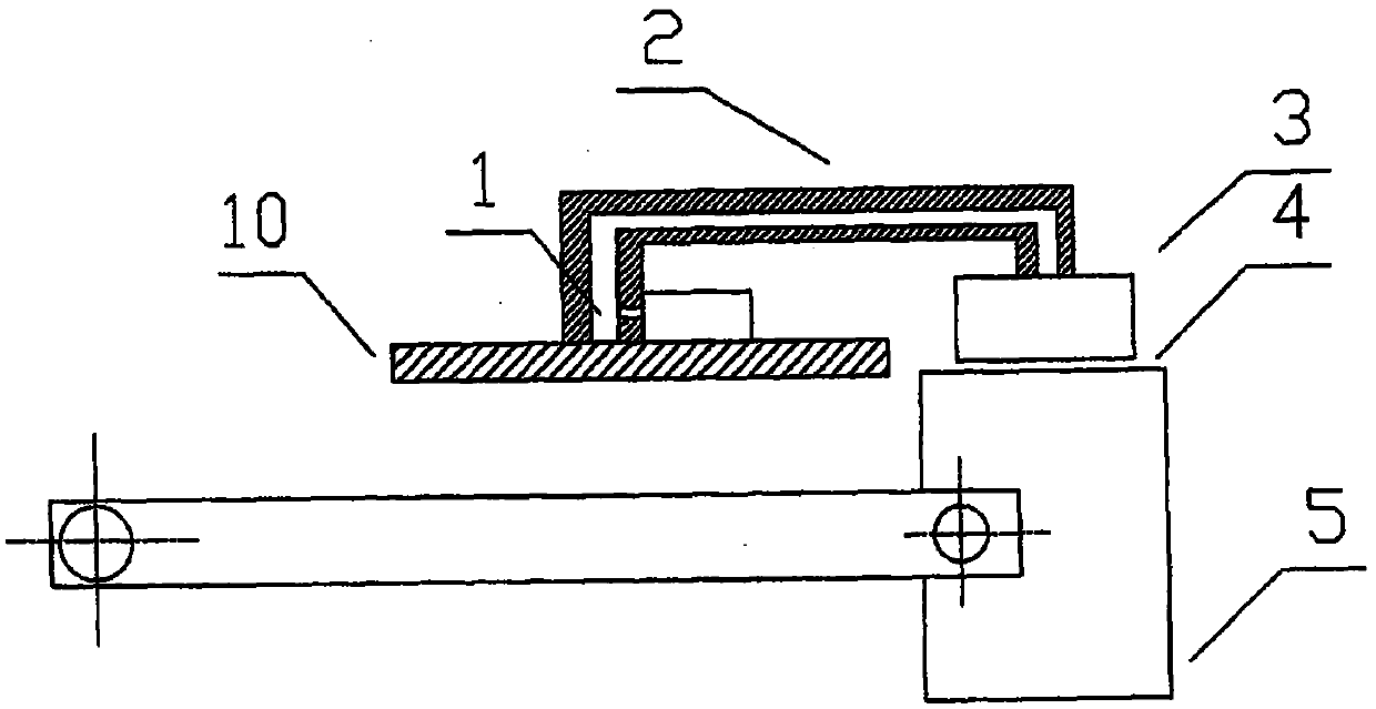
[0025] Refer to attached figure 1 , the fast valve magnetically controlled gravity emergency driving device of the present invention includes a driving device body and a mechanical framework matched with the fast valve;

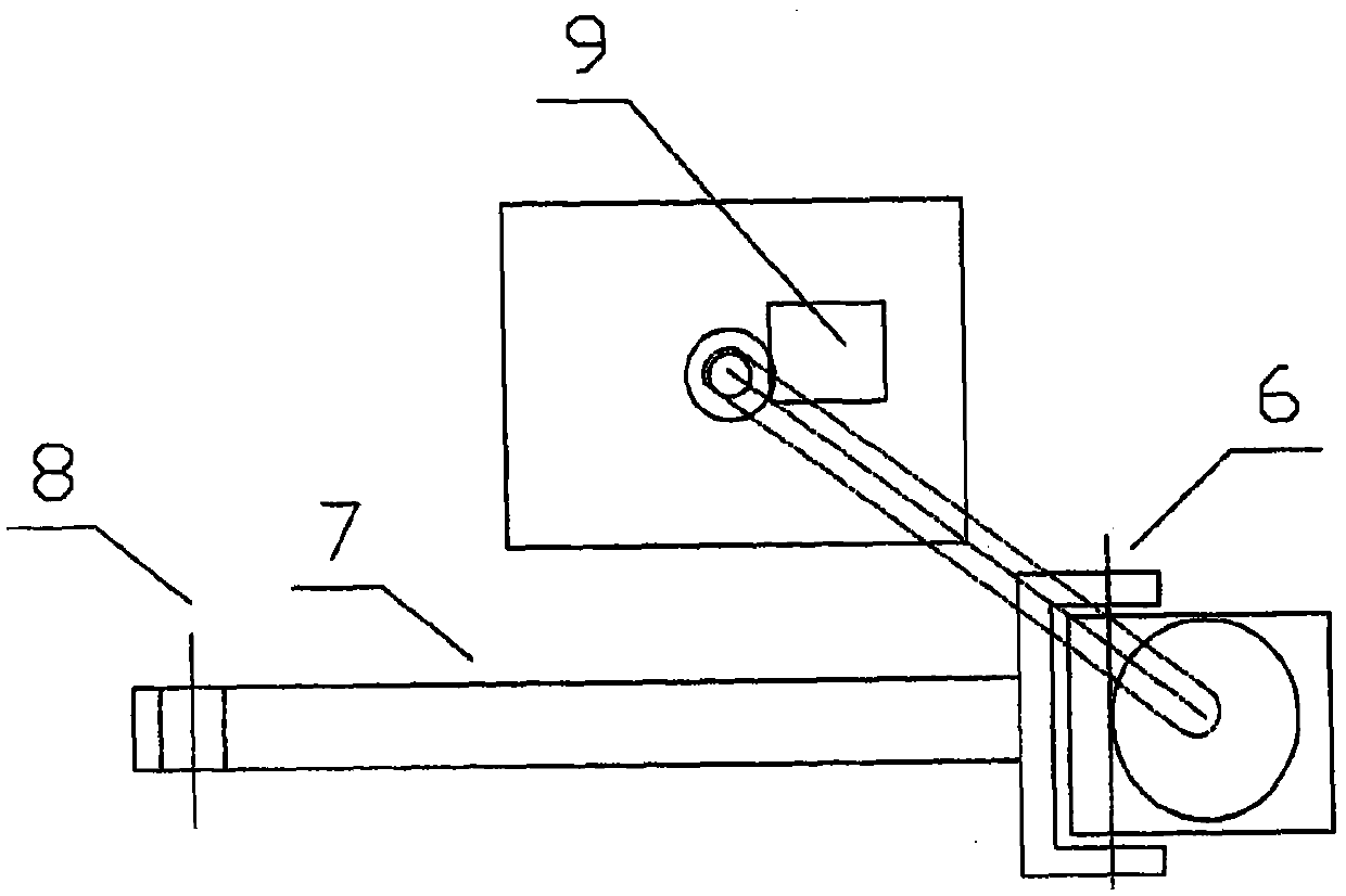
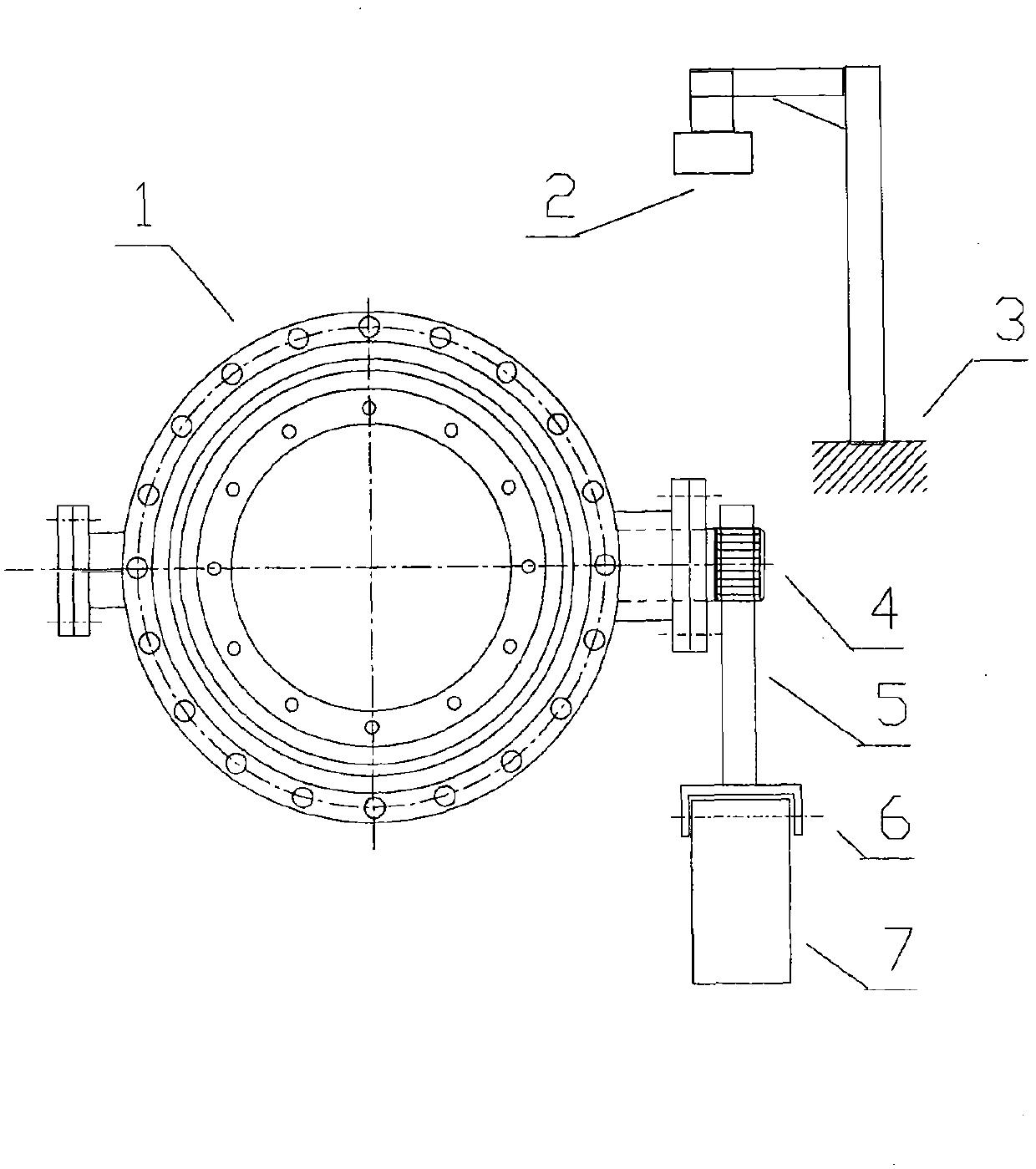
[0026] The main body of the fast valve magnetron gravity emergency driving device includes a magnetron chuck 3, and the cable of the magnetron chuck 3 passes through the magnetron chuck cable channel 1 inside the magnetron chuck steel frame 2 and the magnetic field program Controller 9 ( figure 2 ) to realize the communication connection. When combined with lever arm 7( figure 2 ) After the counterweight 5 movably connected to the connecting pin 6 contacts the magnetron sucker 3, the magnetic field program controller 9 ( figure 2 ) is magne...


PUM


Abstract

The invention discloses a quick-valve magnetic control gravity emergency drive device which comprises a quick valve body, a valve spool, a moment arm lever, a counter weight and a magnetic controller chuck and a magnetic field program controller thereof. Emergency shifting of the valve spool in the valve body is completed automatically depending on external gravity moment, the weight generating the gravity moment and the moment arm lever thereof are attracted together and locked by the magnetic controller chuck to keep torque on a valve spool shaft in balance and keep a set process state of a quick valve, after the magnetic controller chuck is demagnetized under the condition of automatic control, the state of the valve spool is changed by the gravity moment generated by the released counter weight and a drive lever, and the flow state is switched. The device has the advantages that the flow state is quickly and automatically changed in emergencies so as to automatically and safely regulate pipeline flow, hidden danger of possibly caused flow overpressure, fire disasters and contamination accidents can be eliminated, and the flow can be automatically regulated even if under the fire disasters and the like, in order to avoid danger in emergencies.

Description

technical field [0001] The invention relates to a fast valve magnetic control gravity emergency driving device, more specifically, the invention relates to an automatic safety equipment for emergency prevention, control and avoidance of the process of production storage tanks and pipelines of dangerous chemicals such as gas, water conservancy, and petrochemical industries . Background technique [0002] At present, the pipeline valve technology used in the production, storage and transportation of hazardous chemicals such as PetroChina and Sinopec is relatively primitive, and most of the driving methods rely on manpower, hydraulic systems, gas storage pneumatic systems, electric and combined transmission modes. Numerous production practices and accident cases have proved that there are defects and obvious hidden dangers in the control of existing pipeline process valves, high requirements for mechanical transmission, high failure rate, high maintenance cost, high cost of sup...

Claims


Application Information

Patent Timeline
IPC IPC(8): F16K31/00F16K31/02F16K17/36F16K17/12F16K17/168
CPCF16K17/36F16K17/12F16K17/168F16K31/02F16K31/0675
Inventor 朱志强
Owner 天津市塘沽津滨阀门有限公司
Learn More