Heat pump system

A heat pump system and heating mode technology, applied in heat pumps, lighting and heating equipment, damage protection, etc., can solve problems such as indoor temperature fluctuations and reduced indoor comfort

Active Publication Date: 2014-04-23
DANFOSS MICRO CHANNEL HEAT EXCHANGER JIAXING
View PDF14 Cites 12 Cited by
  • Summary
  • Abstract
  • Description
  • Claims
  • Application Information

AI Technical Summary

Problems solved by technology

[0007] But for each defrosting stage, the heating mode will be stopped, and the indoor temperature wil

Method used


Image

  • Heat pump system
  • Heat pump system
  • Heat pump system

Examples


Embodiment Construction

[0052] Through the following examples, combined with the attached Figure 3-14b , the technical solution of the present invention will be further specifically described. In the specification, the same or similar reference numerals designate the same or similar components. The following description of the embodiments of the present invention with reference to the accompanying drawings is intended to explain the general inventive concept of the present invention, but should not be construed as a limitation of the present invention.

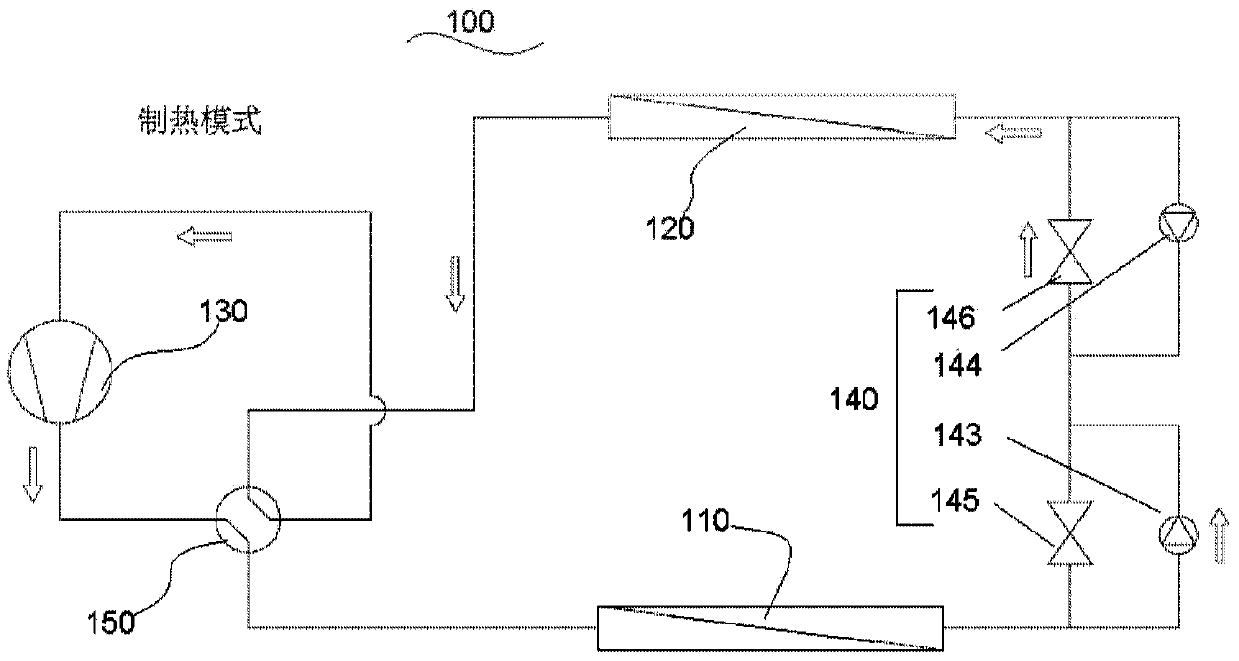
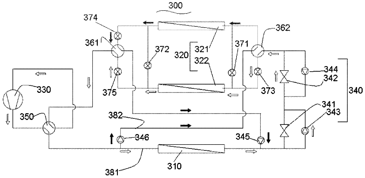
[0053] see image 3 , shows a schematic diagram of a heat pump system 300 according to a first embodiment of the present invention. It can be known that the heat pump system 300 is running in the heating mode. Heat pump system 300 includes at least one reversing valve 350 (shown here as an example as a four-way valve), at least one indoor heat exchanger 310 , at least one outdoor heat exchanger 320 , compressor 330 and at least one throttling dev...


PUM


Abstract

The invention provides a heat pump system. The heat pump system comprises at least one reversing valve, a compressor, at least one indoor heat exchanger, at least one outdoor heat exchanger and at least one throttling device. The outdoor heat exchanger comprises at least two independent flow paths and has three alternative work patterns, wherein the at least two independent flow paths in the outdoor heat exchanger respectively run as an evaporator when the first work pattern is selected, at least one of the at least two independent flow paths in the outdoor heat exchanger is at least partly used for defrosting and the rest of the at least two independent flow paths respectively run as the evaporator when the second work pattern is selected, and the at least two independent flow paths in the outdoor heat exchanger respectively run as a condenser when the third work pattern is selected.

Description

technical field [0001] The invention relates to the technical field of refrigeration and air conditioning, in particular to a heat pump system used in the technical field of refrigeration and air conditioning. Background technique [0002] In a heat pump system, the flow direction of the refrigerant or refrigerant through the evaporative heat exchanger and the condensing heat exchanger can be reversed to allow for the extraction of heat from the target space (cooling mode) and for the injection of heat into the target space (heating mode). ). For example, in cooling mode, refrigerant in the gas phase may flow from the compressor in a first direction to the outdoor unit, which condenses the refrigerant. The liquid refrigerant may then flow through the throttling device to the indoor unit, which evaporates the refrigerant to cool the space. Therefore, in cooling mode, the outdoor unit acts as a condenser and the indoor unit acts as an evaporator. Accordingly, in heating mod...

Claims


Application Information

Patent Timeline
IPC IPC(8): F25B30/02F25B47/02F25B41/04F25B41/06F25B41/20F25B41/30F25B41/31
Inventor 陆向迅杰弗里·L·塔克
Owner DANFOSS MICRO CHANNEL HEAT EXCHANGER JIAXING
Why Eureka
Try Eureka