
Condenser for household refrigerator

A technology for condensers and refrigerators, which is used in household refrigeration devices, evaporators/condensers, household appliances, etc., can solve the problem that the condensed liquid film in the tube cannot be discharged in time, the refrigerant flow resistance in the tube is large, and the condensation heat transfer efficiency is low, etc. problems, to achieve the effect of thinning the flow boundary layer, improving the refrigeration performance and energy efficiency level, and increasing the dryness

Inactive Publication Date: 2014-04-23
CHANGHONG MEILING CO LTD
View PDF8 Cites 0 Cited by
  • Summary
  • Abstract
  • Description
  • Claims
  • Application Information

AI Technical Summary

Problems solved by technology

This vertically arranged "serpentine tube" condenser has a simple structure and high reliability, but it also has many disadvantages: the single vertical tube arrangement causes the condensed liquid film in the tube to not be discharged in time, and the U-shaped bend at the lower part of the vertical tube is easy to Effusion, the flow resistance of the refrigerant in the tube is large, the condensation heat transfer efficiency is low, and the energy consumption of the whole machine is high

Method used


Image

  • Condenser for household refrigerator
  • Condenser for household refrigerator
  • Condenser for household refrigerator

Examples


Embodiment 1

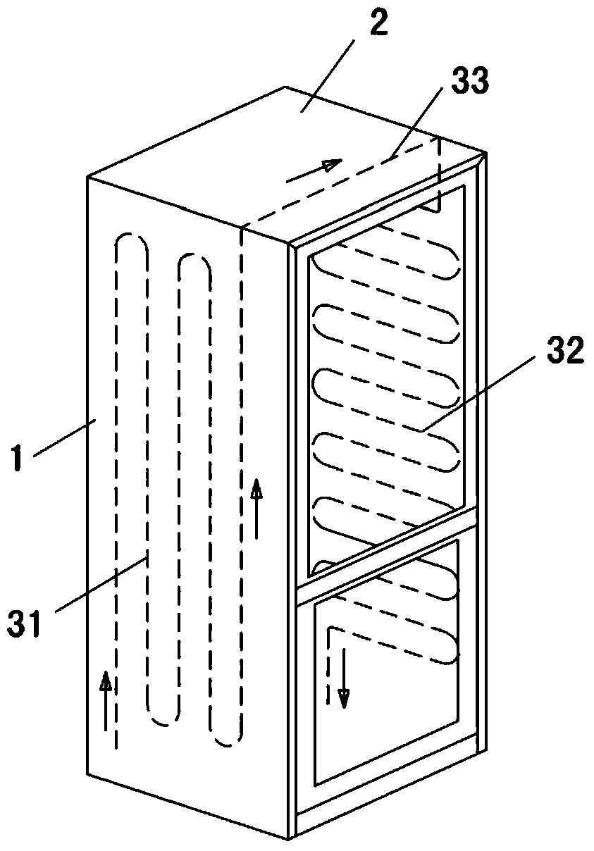
[0024] Such as figure 1 , figure 2 As shown, the condenser in this embodiment includes a vertically arranged condenser front coil 31 and a horizontally arranged condenser rear coil 32; the condenser front coil 31 and the condenser rear coil 32 are respectively attached and fixed to different refrigerators of the refrigerator. Inside the side plate 1 , the coiled pipe 31 at the front section of the condenser and the coiled pipe 32 at the rear section of the condenser are integrally arranged, and the two are connected by a condenser jumper pipe 33 arranged inside the top plate 2 of the refrigerator. The high-temperature refrigerant vapor discharged from the compressor 4 flows through the coiled pipe 31 at the front section of the condenser to the coiled pipe 32 at the rear section of the condenser; the flow direction of the refrigerant in the coiled pipe 32 at the rear section of the condenser is from top to bottom. In specific implementation, different refrigerator side panel...

Embodiment 2

[0030] Such as Figure 4 , Figure 5 As shown, the condenser in this embodiment includes a vertically arranged condenser front coil 31 and a horizontally arranged condenser rear coil 32; the condenser front coil 31 and the condenser rear coil 32 are respectively attached and fixed on the left and right sides of the refrigerator In a refrigerator side panel 1; the coiled pipe 31 of the front section of the condenser and the coiled pipe 32 of the rear section of the condenser are arranged in separate parts, and the two are welded through the connecting pipe 34. The high-temperature refrigerant vapor discharged from the compressor 4 flows through the coiled pipe 31 at the front section of the condenser to the coiled pipe 32 at the rear section of the condenser; the flow direction of the refrigerant in the coiled pipe 32 at the rear section of the condenser is from top to bottom.

[0031] Figure 5 It is a schematic diagram of the refrigerator after assembly and molding. The pip...


PUM


Abstract

The invention discloses a condenser for a household refrigerator. The condenser is characterized by comprising front-end coil condenser pipes vertically arranged and rear-end coil condenser pipes transversely arranged, wherein the front-end coil condenser pipes and the rear-end coil condenser pipes are respectively fixedly attached to different lateral plates of the household refrigerator and condensing agents flow from the front-end coil condenser pipes to the rear-end coil condenser pipes. The condenser consists of the front-end coil condenser pipes and the rear-end coil condenser pipes, thereby achieving a timely discharge of condensation liquid films of the condensing agents inside pipes, decreasing condensation liquid in the U-shaped curved parts of pipes, reducing flow resistance against the condensing agents inside pipes, enhancing the condensation and heat-exchange process of condensing agent vapor inside the condensing pipes, and effectively improving refrigeration performance and level of energy efficiency of household refrigerators or refrigerating cabinets.

Description

technical field [0001] The invention relates to a condenser, in particular to a condenser suitable for household refrigerators or refrigerators, and belongs to the technical field of refrigerator design. Background technique [0002] Household refrigerators usually use vapor compression refrigeration. The refrigeration system consists of a compressor, a condenser, a throttling mechanism, and an evaporator. The high-temperature and high-pressure refrigerant vapor discharged from the compressor enters the condenser pipeline, and through the condensation and heat exchange in the tube, the enthalpy of the refrigerant decreases, and gradually changes from a gaseous condensed phase to a liquid refrigerant, and then the liquid refrigerant is throttled and depressurized by the throttling device , into the evaporator of the refrigerator, and the evaporation and heat absorption process is realized in the evaporator. The refrigerant is completely evaporated into steam and then sucked b...

Claims


Application Information

Patent Timeline
IPC IPC(8): F25B39/04F25D19/00
Inventor 魏邦福白连社刘佳李建周
Owner CHANGHONG MEILING CO LTD
Learn More