Immunity testing device for electric energy meters

A technology for testing devices and electric energy meters, which is applied to measurement devices, measuring electrical variables, instruments, etc., can solve problems such as expensive testing equipment, increased testing time for equipment connecting lines, and testing costs, and achieves stable and reliable placement. The effect of testing costs and saving testing time

Active Publication Date: 2014-04-23
SHENZHEN STAR INSTR
View PDF4 Cites 1 Cited by
  • Summary
  • Abstract
  • Description
  • Claims
  • Application Information

AI Technical Summary

Problems solved by technology

During the test process, according to the standard, the length of the cable that the tested product needs to be exposed to the electromagnetic field is 1M. During the test, the length of the equipment cable is too long and the equipment connection line is complicated, which makes it difficult to distinguish the line condition, which affects the quality of the line. Fast and accurate connection, and if the ...

Method used


Image

  • Immunity testing device for electric energy meters
  • Immunity testing device for electric energy meters

Examples


Embodiment Construction

[0026] In order to describe the technical content, structural features, achieved goals and effects of the present invention in detail, the following will be described in detail in conjunction with the embodiments and accompanying drawings.

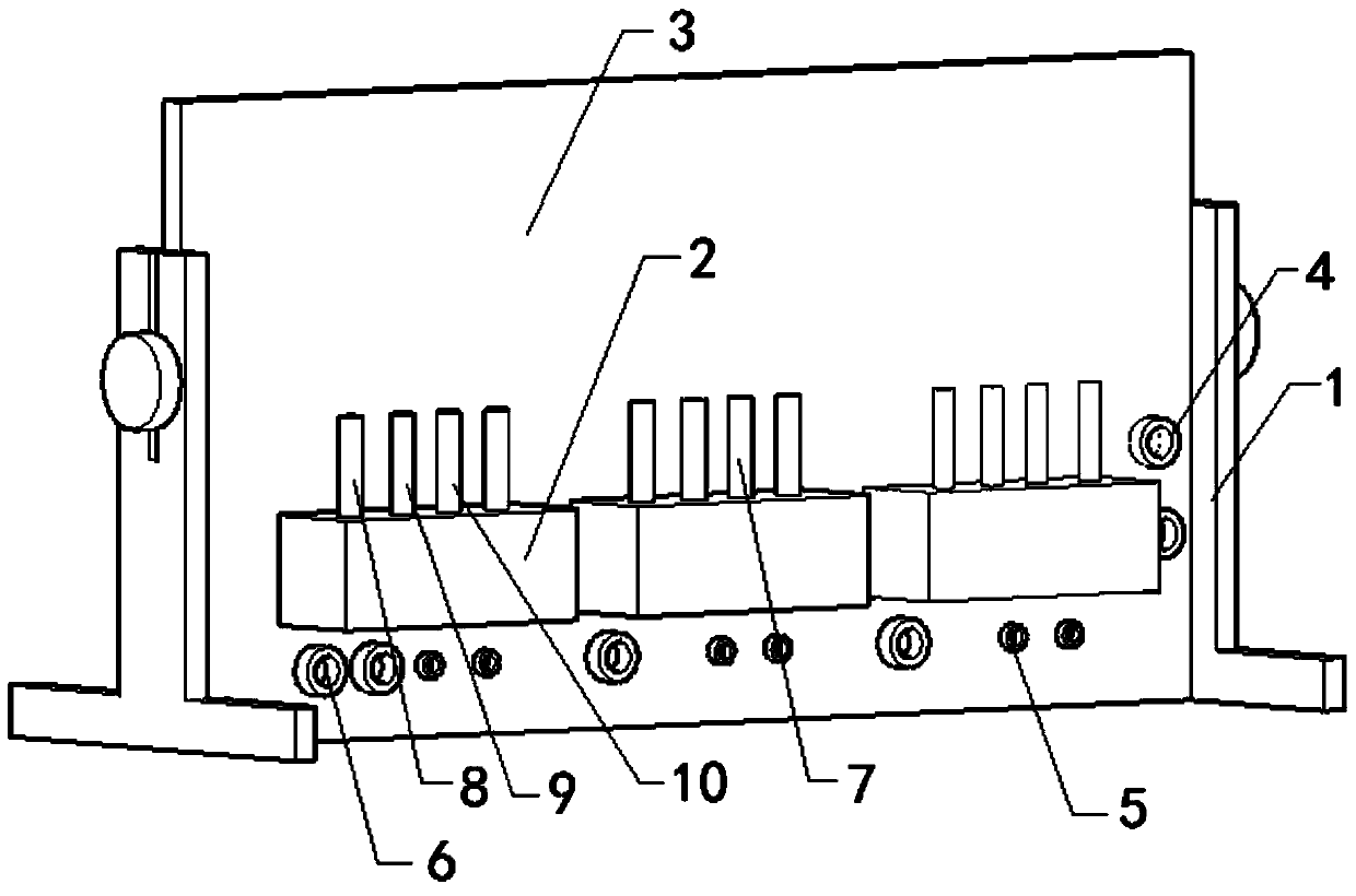
[0027] see figure 1 , a kind of electric energy meter immunity test device of the present invention, comprises support base 1, tailstock 2, back plate 3, current connection terminal 4, pulse terminal 5, voltage connection terminal 6, terminal post 7, positive terminal post 8, Negative terminal 9 and voltage terminal 10.

[0028] The backboard 3 is fixed on the support base 1, the tailstock 2 is fixed on the backboard 3, and the backboard 3 is provided with a current terminal 4, a pulse terminal 5 and a voltage terminal 6; the voltage terminal 6 includes a voltage live wire L terminal and voltage zero line N terminal, pulse terminal 5 includes pulse output positive terminal and pulse output negative terminal, current terminal 4 includes cu...


PUM


Abstract

The invention discloses an immunity testing device for electric energy meters. The device comprises a bracket seat, tailstocks and a back plate, wherein the back plate is fixedly arranged on the bracket seat; the tailstocks are fixedly arranged on the back plate; current connection terminals, pulse terminals and voltage connection terminals are arranged on the back plate, and are electrically connected with electric energy meter detection equipment respectively; wiring terminals are arranged on each tailstock, and comprise one or more than one positive wiring terminal, a negative wiring terminal and a voltage wiring terminal; the positive and negative wiring terminals are connected in series; the front positive wiring terminal is connected with a positive current connection terminal, and the tail negative wiring terminal is connected with a negative current connection terminal; the voltage wiring terminals are connected in parallel; a voltage live wire L connection terminal is electrically connected with the front positive wiring terminal, and the voltage wiring terminals are electrically connected with a voltage null line N connection terminal respectively. According to the device, equipment can be more rapidly connected during high-frequency electromagnetic field immunity testing, and the lengths of connecting wires are maximally reduced to reduce high-frequency interference.

Description

technical field [0001] The invention relates to a testing device for an electric energy meter, in particular to an anti-disturbance testing device for an electric energy meter. Background technique [0002] In order to ensure the anti-static discharge interference ability of electrical and electronic products when they are subjected to high-frequency electromagnetic interference, electrical and electronic products must undergo high-frequency electromagnetic field immunity testing. The currently known high-frequency electromagnetic field immunity testing equipment for electric energy meters is It is composed of electric energy meter inspection device, signal generator, power amplifier and antenna. The test process must be carried out in an anechoic chamber. The signal generator generates the frequency signal required by the standard of 80MHz to 2000MHz for the test. After the power is amplified by the power amplifier, the uniformity test site required by the test standard is ...

Claims


Application Information

Patent Timeline
IPC IPC(8): G01R35/04
Inventor 李向锋张平龙代文
Owner SHENZHEN STAR INSTR
Why Eureka
Try Eureka