
Optical Proximity Correction Method for Improving Process Window

A technology of optical proximity correction and process window, applied in the field of optical proximity correction, which can solve the problem of not considering the size error of reticle

Active Publication Date: 2016-09-07
SHANGHAI HUALI MICROELECTRONICS CORP
View PDF8 Cites 0 Cited by
  • Summary
  • Abstract
  • Description
  • Claims
  • Application Information

AI Technical Summary

Problems solved by technology

[0008] However, the traditional model-based OPC method generally considers the influence of EPE (Edge Placement Error), but does not consider the impact of changes in mask size errors, lithographic condition deviations, etc. on the accuracy of OPC.

Method used


Image

  • Optical Proximity Correction Method for Improving Process Window
  • Optical Proximity Correction Method for Improving Process Window
  • Optical Proximity Correction Method for Improving Process Window

Examples


Embodiment Construction

[0027] In order to make the content of the present invention clearer and easier to understand, the content of the present invention will be described in detail below in conjunction with specific embodiments and accompanying drawings.

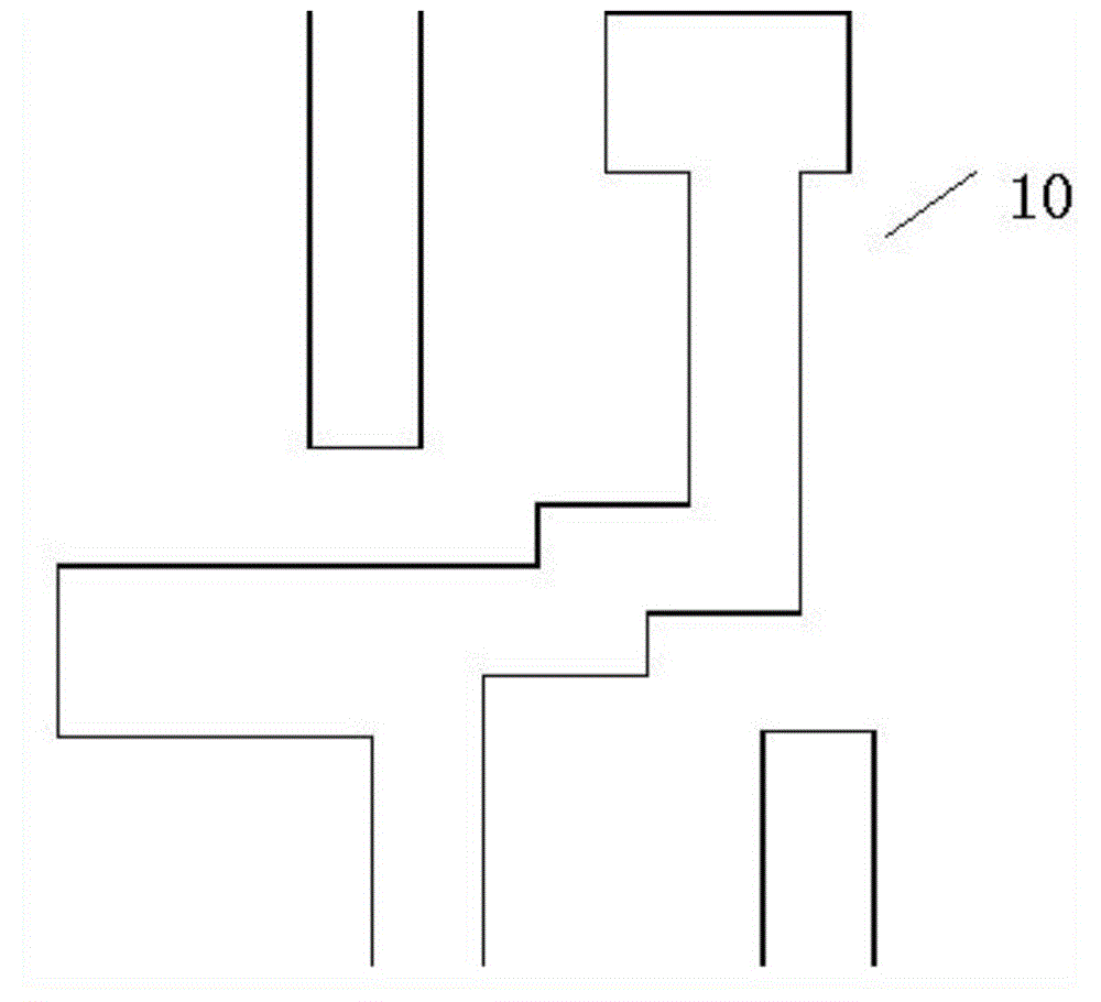
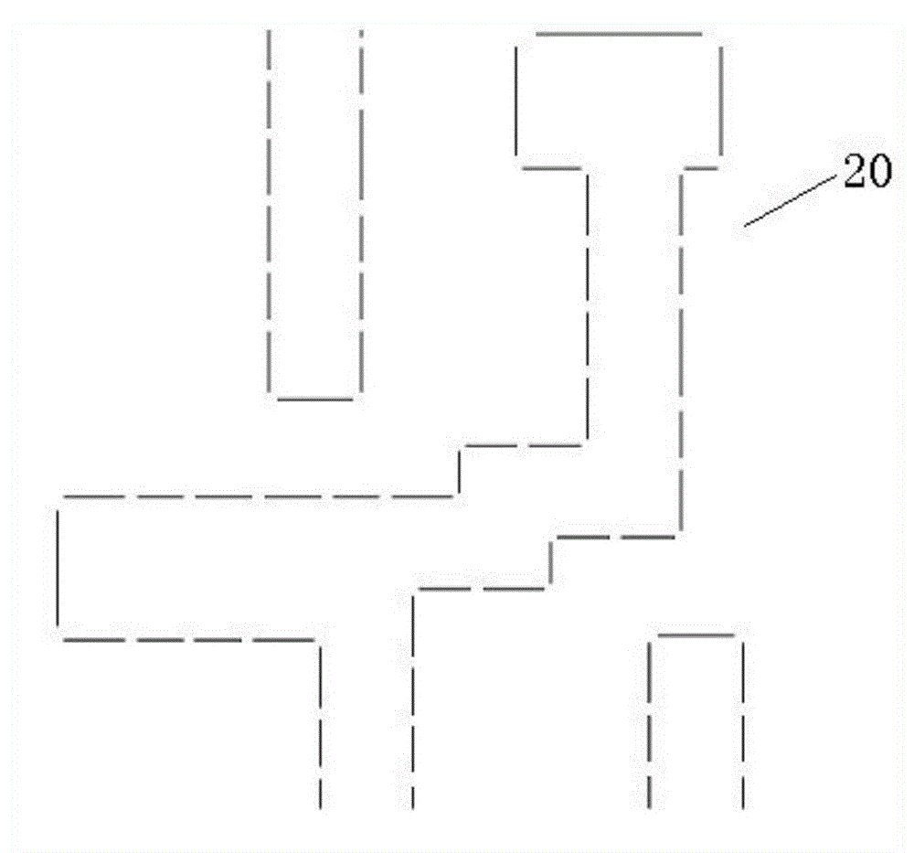
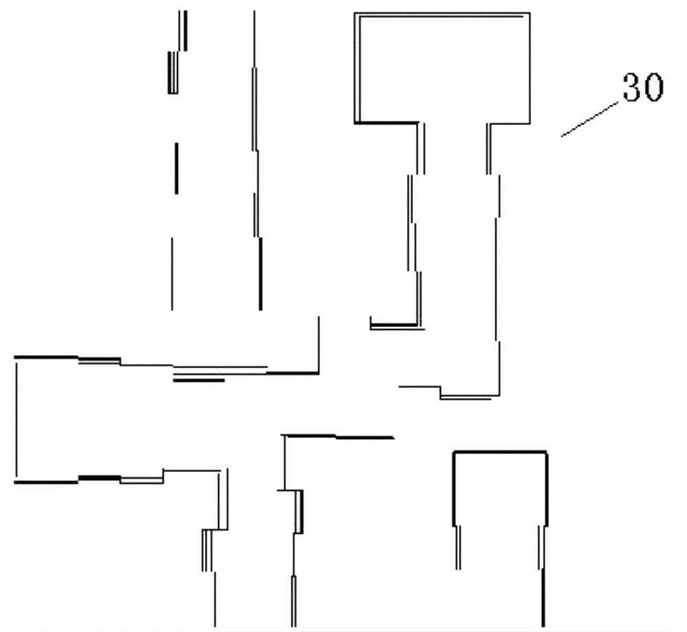
[0028] At present, the general model-based optical proximity correction OPC processing flow is as follows: firstly, the target graphics 10 (such as figure 1 ) for input, and then according to certain rules to cut the edge of the target graph into line segments, such as figure 2 As shown; the cut line segment 20 can be offset or corrected according to a certain calculation method, such as image 3 shown; before correction, the imaging result of the target figure is simulated 50 (such as Figure 5 ), correct according to the deviation (EPE) between the simulated contour and the target graphic, and then simulate again after correction and compare it with the target graphic. If several rounds are repeated, the final optical proximity correction O...


PUM


Abstract

The invention discloses an optical proximity correction method for improving a process window. The method comprises the following steps: 1, inputting a target graph and cutting the target graph; 2, simulating the target graph and calculating initial values of first to third parameters; 3, setting the parameters; 4, correcting according to the current value of the first parameter to obtain a corrected graph, recalculating to obtain the updated values of the first to third parameters, and calculating a corrected comprehensive error; 5, judging whether the corrected comprehensive error is not more than a maximum permissible error, and judging whether the frequency of performing the step 4 is equal to or more than a maximum correction frequency; when a judgment result in the step 5 is that the corrected comprehensive error is more than the maximum permissible error and the frequency of performing the step 4 is less than the maximum correction frequency, re-performing the steps 4 and 5.

Description

technical field [0001] The present invention relates to the field of semiconductor manufacturing, and more specifically, the present invention relates to an optical proximity correction (Optical Proximity Correction, OPC for short) method for improving a process window. Background technique [0002] With the continuous development of integrated circuit technology, computational lithography has become an indispensable part of reticle data preparation and data verification. At the 65nm / 55nm node, more than half of the reticle needs to introduce computational lithography methods for data preparation And data verification, and at 20nm, almost all reticles need to apply computational lithography. Under the trend of shrinking feature size (CD), various new and more complex RET (Resolution Enhancement Technology) have also emerged, such as double-level or multi-level exposure, model-based auxiliary graphics, pixelated exposure wide However, the model-based optical proximity correc...

Claims


Application Information

Patent Timeline
Patent Type & Authority Patents(China)
IPC IPC(8): G03F1/36
Inventor 何大权王伟斌顾婷婷魏芳张旭升
Owner SHANGHAI HUALI MICROELECTRONICS CORP
Learn More