Method and device for controlling the high-precision synchronous movement of the cantilever beam of a fully automatic placement machine along the y-axis

A high-precision synchronization and placement machine technology, applied in the direction of comprehensive factory control, comprehensive factory control, electrical program control, etc., can solve the problem of asynchronous movement speed and displacement at both ends of the cantilever beam

Active Publication Date: 2016-02-17
HARBIN INST OF TECH
View PDF5 Cites 0 Cited by
  • Summary
  • Abstract
  • Description
  • Claims
  • Application Information

AI Technical Summary

Problems solved by technology

[0003] The invention aims to solve the problem that the moving speed and displacement of the two ends of the cantilever beam are not synchronized during the movement of the cantilever beam of the automatic placement machine along the Y-axis direction, and now provides a high-precision Method and device for synchronous motion

Method used


Image

  • Method and device for controlling the high-precision synchronous movement of the cantilever beam of a fully automatic placement machine along the y-axis
  • Method and device for controlling the high-precision synchronous movement of the cantilever beam of a fully automatic placement machine along the y-axis

Examples


specific Embodiment approach 1

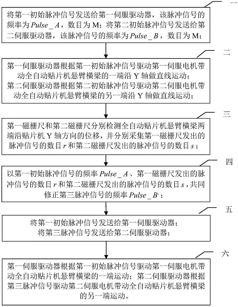
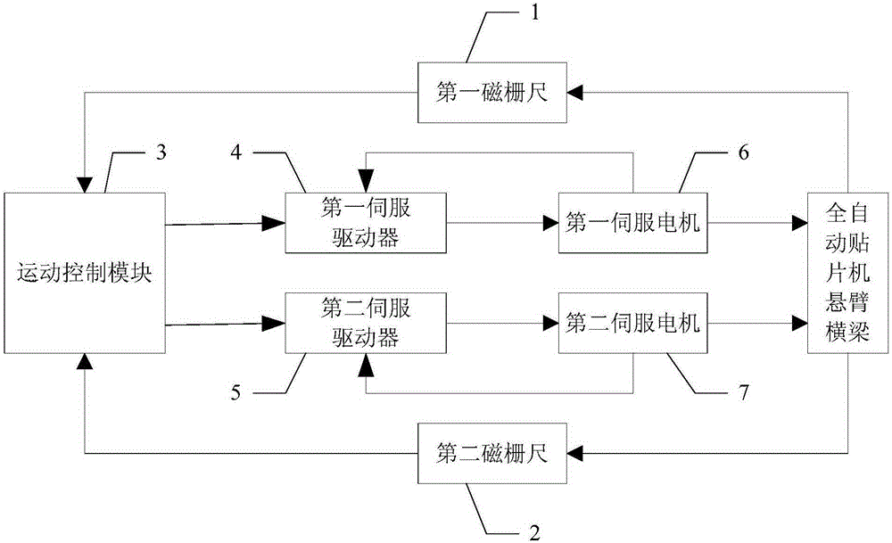
[0044] Specific implementation mode one: refer to figure 1 Describe this embodiment in detail. The method for controlling the cantilever beam of a fully automatic placement machine to move synchronously with high precision along the Y-axis described in this embodiment is implemented based on the following device, which includes: a first magnetic Scale 1, second magnetic scale 2, first servo driver 4, second servo driver 5, first servo motor 6 and second servo motor 7;

[0045] The first magnetic scale 1 is used to detect the displacement of one end of the cantilever beam of the automatic placement machine along the Y-axis direction of the placement machine;

[0046] The second magnetic scale 2 is used to detect the displacement of the other end of the cantilever beam of the automatic placement machine along the Y-axis direction of the placement machine;

[0047] The first servo driver 4 is used to drive the first servo motor 6 to move, and the first servo driver 4 also collec...

specific Embodiment approach 2

[0060] Specific embodiment 2: This embodiment is a further description of the method for controlling the cantilever beam of a fully automatic placement machine along the Y-axis with high precision and synchronous movement described in specific embodiment 1. In this embodiment, the first step is obtained in step 4. The method of the frequency Pulse_B' of the three pulse signals is:

[0061] Pulse_B'=Pulse_A+P*(r-s),

[0062] where P is the proportionality coefficient.

specific Embodiment approach 3

[0063] Specific implementation mode three: refer to figure 2 Describe this embodiment in detail. The device for controlling the cantilever beam of a fully automatic placement machine to move synchronously along the Y axis with high precision described in this embodiment includes: a first servo driver 4, a second servo driver 5, a first servo Motor 6 and second servo motor 7;

[0064] The first servo driver 4 is used to drive the first servo motor 6 to move, and the first servo driver 4 also collects the output speed and rotor position of the first servo motor 6, and the first servo motor 6 is used to drive the automatic placement machine One end of the cantilever beam moves linearly along the Y axis;

[0065] The second servo driver 5 is used to drive the second servo motor 7 to move, and the second servo driver 5 also collects the output speed and rotor position of the second servo motor 7, and the second servo motor 7 is used to drive the automatic placement machine The o...


PUM


Abstract

A method and a device for controlling the cantilever crossbeam of a full automatic chip mounter to perform high-precision synchronous motion along the Y axis relate to the field of chip mounter control and aim to solve the problem that in the motion process of the cantilever crossbeam of the full automatic chip mounter along the Y axis, moving speeds and displacement of two ends of the cantilever crossbeam are asynchronous. According to the method and device for controlling the cantilever crossbeam of the full automatic chip mounter to perform high-precision synchronous motion along the Y axis, signals collected by a first magnetic railing ruler and a second magnetic railing ruler are guided into a motion control module, and a pulse signal sent to a second servo driver is revised by using software in the motion control module, so the aim of compensating the pulse error of the two magnetic railing rulers to the second servo driver in a mode of amending a pulse frequency in the shortest sampling time is ensured, and the moving speeds of the two ends of the cantilever crossbeam are controlled to be same. The method and device for controlling the cantilever crossbeam of the full automatic chip mounter to perform high-precision synchronous motion along the Y axis are suitable for controlling the cantilever crossbeam of the full automatic chip mounter to move along the Y axis.

Description

technical field [0001] The invention belongs to the field of chip mounter control. Background technique [0002] The fully automatic placement machine is the most important and most complex equipment on the entire (SMTSurfaceMountedTechnology, surface mount technology) production line. The motion control system of the automatic placement machine is divided into four parts: X, Y, Z, and θ axes. The automatic placement machine has high requirements on the control of the Y-axis, and the bilateral position error of the cantilever beam is required to be within 0.3mm during operation. Exceeding this error will not only affect the placement accuracy of the chip but also cause damage to the mechanical structure such as the cantilever beam. Arch-type structure automatic placement machine, the cantilever beam moves along the Y-axis direction, and the span of the cantilever beam is relatively large. If the cantilever beam is driven on one side, the mechanical requirements are too high...

Claims


Application Information

Patent Timeline
Patent Type & Authority Patents(China)
IPC IPC(8): G05B19/418
CPCY02P90/02
Inventor 高会军孙光辉徐世东王晗宇余洋谢文麟张增杰
Owner HARBIN INST OF TECH
Why Eureka
Try Eureka