A stator core ventilation ditch structure

A stator core and ventilation ditch technology, which is applied to the shape/style/structure of the magnetic circuit and the static parts of the magnetic circuit, etc., can solve the problem of insufficient heat exchange between the cooling gas and the ventilation slots, and insufficient heat dissipation area of ​​the ventilation slots. The cooling gas disturbance is not strong enough to improve the cooling effect, the overall structural strength is high, and the cooling effect is improved

Active Publication Date: 2015-09-23
STATE GRID XINYUAN +1
View PDF7 Cites 0 Cited by
  • Summary
  • Abstract
  • Description
  • Claims
  • Application Information

AI Technical Summary

Problems solved by technology

[0011] Although the ventilation slots disclosed in this patent document can change the gas flow state in the stator ventilation groove to a certain extent by adding fins, the disturbance effect on the cooling gas is not strong, and the heat dissipation area of ​​the ventilation slots is not significantly increased. , therefore, the heat exchange between the cooling gas and the ventilation slots is not sufficient, and the cooling effect on the stator is not very good

Method used


Image

  • A stator core ventilation ditch structure
  • A stator core ventilation ditch structure
  • A stator core ventilation ditch structure

Examples


Embodiment 1

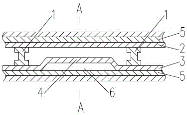
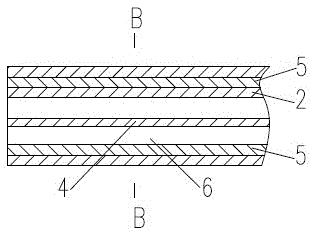
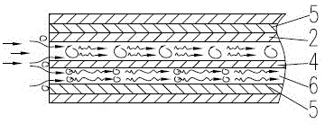
[0067] A stator core ventilation trench structure, including a plurality of repeating structural units, the repeating structural unit is formed by the channel surrounded by the upper ventilation slot piece 2, the lower ventilation slot piece 3 and two adjacent ventilation trench support components 1, the ventilation trench One end of the support member 1 is connected to the upper ventilation slot 2, and the other end is connected to the lower ventilation slot 3, and the upper ventilation slot 2 or the lower ventilation slot 3 has at least one protrusion 4 extending radially along the stator core , the protrusion 4 is located in the channel, the air channel 6 is formed between the protrusion 4 of the upper ventilation slot 2 and the stator core segment 5 adjacent to the upper ventilation slot 2, and the protrusion 4 of the lower ventilation slot 3 An air passage 6 is formed between the stator core segment 5 adjacent to the lower ventilation slot 3 , and the protrusion 4 separate...

Embodiment 2

[0070] A stator core ventilation trench structure, including a plurality of repeating structural units, the repeating structural unit is formed by the channel surrounded by the upper ventilation slot piece 2, the lower ventilation slot piece 3 and two adjacent ventilation trench support components 1, the ventilation trench One end of the support member 1 is connected to the upper ventilation slot 2, and the other end is connected to the lower ventilation slot 3, and the upper ventilation slot 2 or the lower ventilation slot 3 has at least one protrusion 4 extending radially along the stator core , the protrusion 4 is located in the channel, the air channel 6 is formed between the protrusion 4 of the upper ventilation slot 2 and the stator core segment 5 adjacent to the upper ventilation slot 2, and the protrusion 4 of the lower ventilation slot 3 An air passage 6 is formed between the stator core segment 5 adjacent to the lower ventilation slot 3 , and the protrusion 4 separate...

Embodiment 3

[0073] A stator core ventilation trench structure, including a plurality of repeating structural units, the repeating structural unit is formed by the channel surrounded by the upper ventilation slot piece 2, the lower ventilation slot piece 3 and two adjacent ventilation trench support components 1, the ventilation trench One end of the support member 1 is connected to the upper ventilation slot 2, and the other end is connected to the lower ventilation slot 3, and the upper ventilation slot 2 or the lower ventilation slot 3 has at least one protrusion 4 extending radially along the stator core , the protrusion 4 is located in the channel, the air channel 6 is formed between the protrusion 4 of the upper ventilation slot 2 and the stator core segment 5 adjacent to the upper ventilation slot 2, and the protrusion 4 of the lower ventilation slot 3 An air passage 6 is formed between the stator core segment 5 adjacent to the lower ventilation slot 3 , and the protrusion 4 separate...


PUM


Abstract

A ventilating duct structure of a stator core comprises a plurality of repetitive structural units, wherein each repetitive structural unit is formed by a channel which is defined by an upper ventilating slot piece, a lower ventilating slot piece and two adjacent ventilating duct supporting components; one end of each ventilating duct supporting component is connected with the upper ventilating slot piece, and the other end of each ventilating duct supporting component is connected with the lower ventilating slot piece; the upper ventilating slot piece or the lower ventilating slot piece is provided with at least one protuberance which extends in the radial direction of the stator core; the protuberance is positioned in the channel; the protuberance of the upper ventilating slot piece and a stator core fan-shaped piece adjacent to the upper ventilating slot piece define a ventilating path; the protuberance of the lower ventilating slot piece and a stator core fan-shaped piece adjacent to the lower ventilating slot piece define a ventilating path; the protuberances divide the channel into a plurality of ventilation and heat exchange spaces. By improving the ventilating duct structure of the stator core, the cooling effect of a stator is remarkably improved, the flow of cooling gas and loss of ventilation are also greatly reduced, and accordingly, the efficiency of a motor is improved.

Description

technical field [0001] The invention relates to the technical field of motor cooling, in particular to a stator core ventilation groove structure with good cooling effect. Background technique [0002] At present, the energy consumption of motors in my country accounts for 60-70% of industrial energy consumption. From the perspective of energy conservation and environmental protection, high-efficiency motors are the current international development trend. my country's "Twelfth Five-Year Plan" has also increased the research and development of high-efficiency motors . One of the ways to improve the efficiency of the motor is to reduce the loss of the motor. [0003] On the other hand, with the advancement of motor design and manufacturing technology, the capacity and power density of motors continue to increase, and the problems of loss, heat generation and ventilation become more and more serious. In order to ensure the reliable operation and service life of large-capacity...

Claims


Application Information

Patent Timeline
Patent Type & Authority Patents(China)
IPC IPC(8): H02K1/20
Inventor 高苏杰郑小康廖毅刚张天鹏钱昌燕杜国斌黄智欣钱生坤蒋富强
Owner STATE GRID XINYUAN
Why Eureka
Try Eureka