
Cutting insert and cutting tool

一种切削刀片、切削工具的技术,应用在铣削切削刀片、制造工具、弧段工具等方向,达到高效率切削加工、制造成本低廉、牢固工具刚性的效果

Active Publication Date: 2014-04-23
TUNGALOY CORP
View PDF6 Cites 1 Cited by
  • Summary
  • Abstract
  • Description
  • Claims
  • Application Information

AI Technical Summary

Problems solved by technology

The cutting insert of this patent document 2 has a cutting edge portion only on one side, so only one side is used.

Method used


Image

  • Cutting insert and cutting tool
  • Cutting insert and cutting tool
  • Cutting insert and cutting tool

Examples


no. 2 approach

[0086] Next, a second embodiment of the present invention will be described with reference to the drawings. In addition, since the basic structure of this embodiment is the same as that of the said embodiment, only the characteristic structure is demonstrated below.

[0087] Figure 16A , Figure 16B It is a perspective view showing the cutting insert of the present embodiment and an indexable cutting tool to which the cutting insert is mounted. The cutting insert 31 of this embodiment is provided with a notch 32 in a part thereof. In addition, an indexable cutting tool using this cutting insert 32 is provided with a protrusion 33 corresponding to the notch 32 . The notch 32 is provided at a different position when using the front edge and when using the back edge, and by providing the notch 32 , it is possible to prevent the front edge and the back edge from being incorrectly attached to the indexable cutting tool. Thereby, the cutting insert can be efficiently used up to...

no. 3 approach

[0090] Next, a third embodiment of the present invention will be described with reference to the drawings. In addition, since the basic structure of this embodiment is the same as that of the said embodiment, only the characteristic structure is demonstrated below.

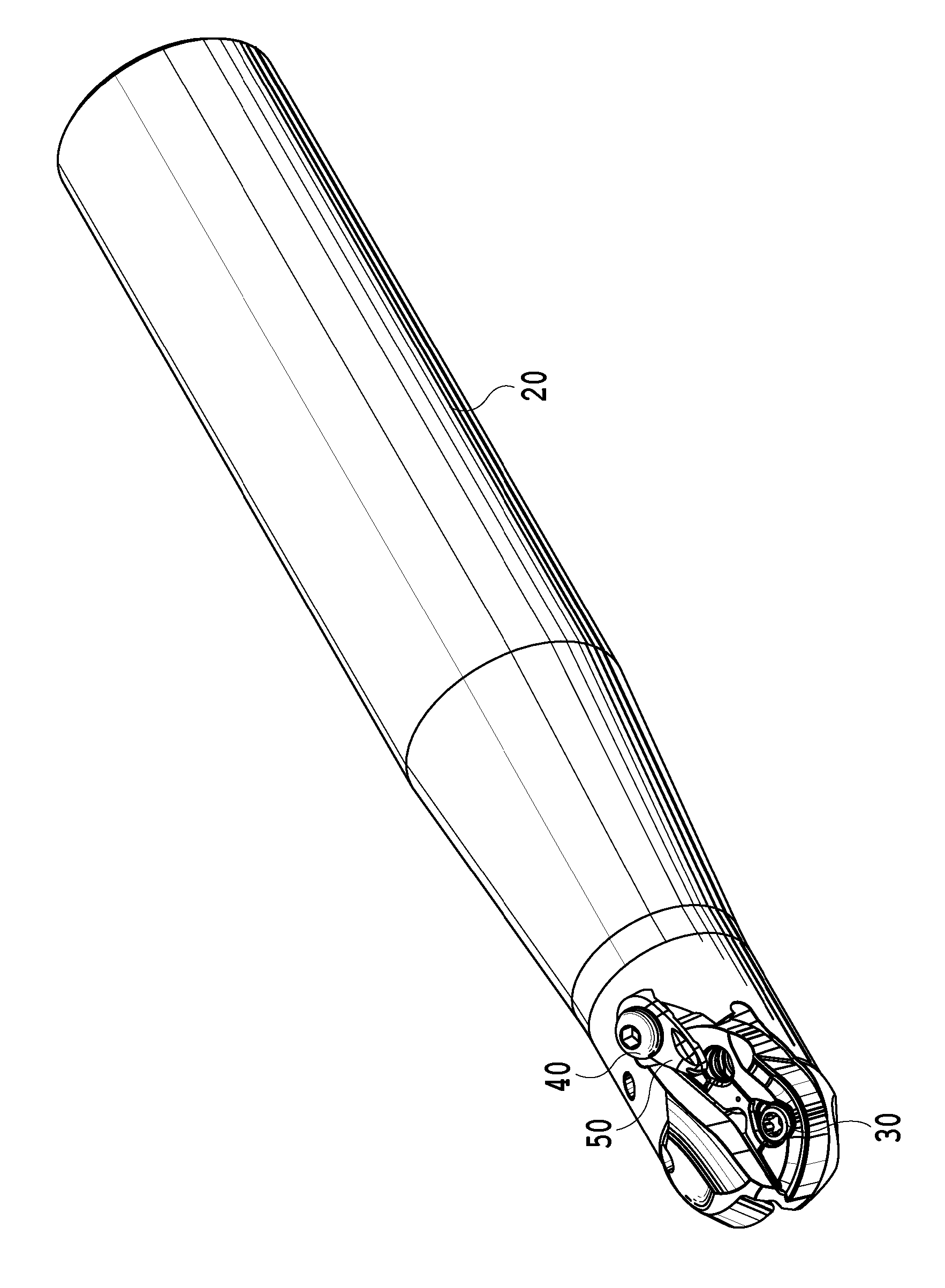
[0091] Figure 17 It is a perspective view showing the cutting insert of the present embodiment and an indexable cutting tool to which the cutting insert is attached. In the first and second embodiments, the cutting insert is attached to the cutting tool with two fastening screws 30, but in this embodiment, the pressing bolt 40 is used in addition to the two fastening screws 30 to further improve the cutting edge. The clamping piece is rigid and mounts to the cutting tool.

[0092] In the cutting tool of this embodiment, by providing a threaded hole for the pressing bolt 40 at a position that does not overlap with the mounted cutting insert, and attaching and tightening the pressing bolt 40 to the threaded hole,...


PUM


Abstract

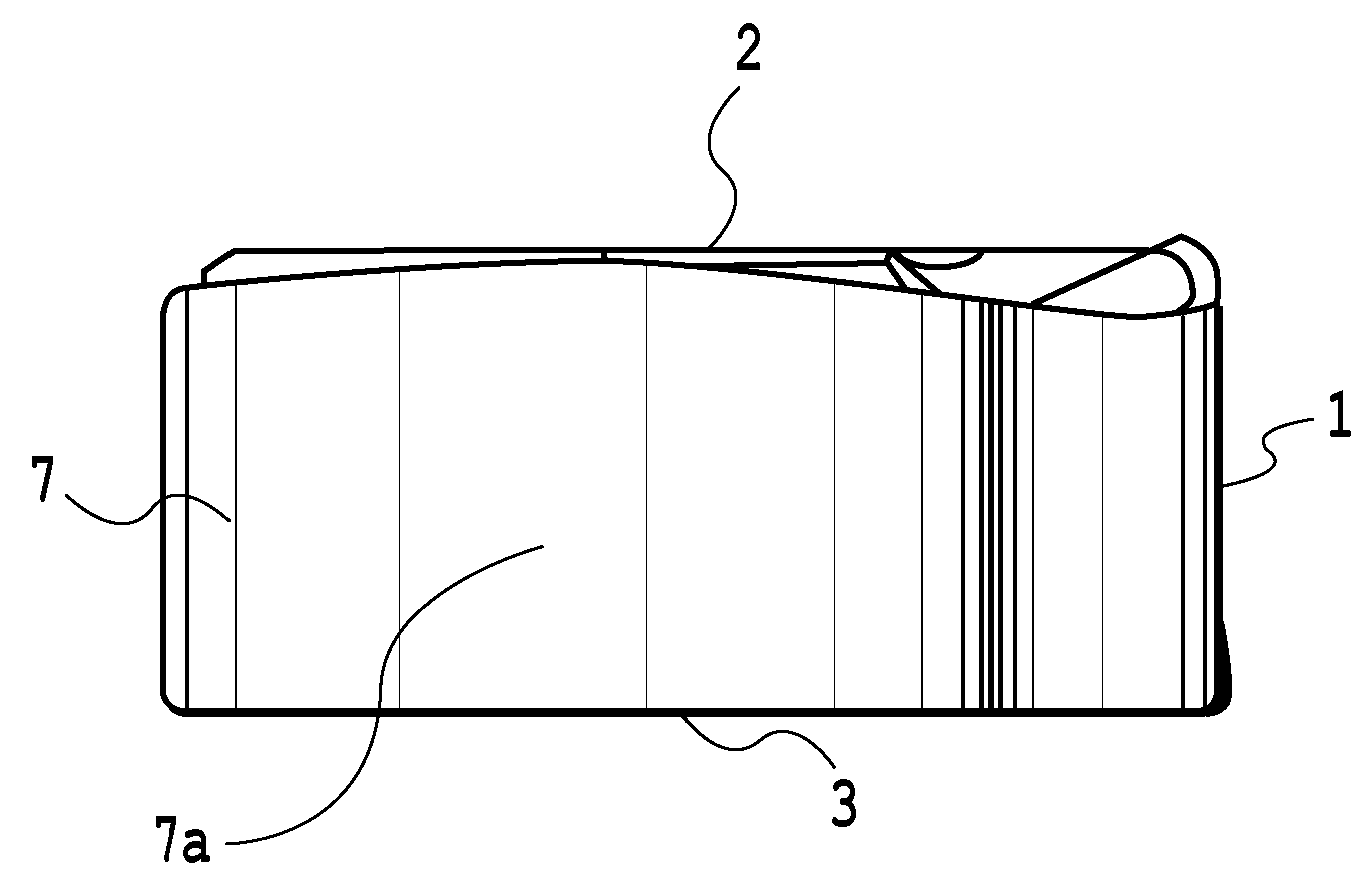
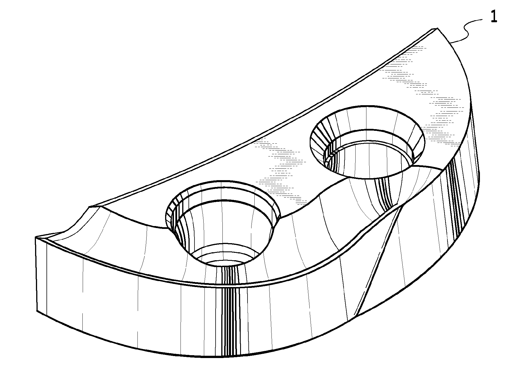
The invention provides a cutting insert and a cutting tool, which have very strong tool rigidity and are capable of highly efficient cutting, and the production cost per one cutting edge of which is low. For this purpose, a first rake face (4a) and a second seating surface (8a) are provided on the upper surface (2) of the cutting insert (1). A second rake face (4b) and a first seating surface (8b) are provided on the lower surface (3) of the cutting insert. The cutting edge is provided with: a first cutting edge portion (5a) formed at the ridge where the first rake face (4a) and a flank (7) intersect; and a second cutting edge portion (6a) formed at the ridge where the second rake face (4b) and the flank (7) intersect. The first cutting edge portion (5a) is provided at a position opposite the ridge where the first seating surface (8b) and the flank (7) intersect, and the second cutting edge portion (6a) is provided at a position opposite the ridge where the second seating surface (8a) and the flank (7) intersect.

Description

technical field [0001] The present invention relates to a cutting insert detachably attached to a bit-replaceable cutting tool body, and a cutting tool detachably attaching the cutting insert. Background technique [0002] As a conventional cutting insert and cutting tool, for example, the cutting insert and cutting tool disclosed in Patent Document 1 are known. That is, the rake face is formed on the upper surface, the flank face is formed on the side face, and the cutting edge is formed on the intersecting ridge line of the rake face and the flank face. In such a cutting insert, the outer shape of the cutting insert is approximately fan-shaped, The cutting edge has a cutting edge portion approximately 1 / 4 arc-shaped. In addition, in this cutting insert, only one rake face is formed on the upper surface, a seating surface is formed on the lower surface, and one mounting hole is formed. In this form, only one cutting edge portion having a substantially 1 / 4 arc shape is for...

Claims


Application Information

Patent Timeline
Patent Type & Authority Applications(China)
IPC IPC(8): B23C5/20B23C5/10
CPCB23C2210/0428B23C5/1045B23C2200/362B23C5/2221B23C5/1027B23C2210/168B23C5/205B23C5/207B23C5/2256Y10T407/192Y10T407/1934Y10T407/235Y10T407/1936Y10T407/1924Y10T407/21B23C5/2213B23C5/202B23C5/2252
Inventor K.S.布哈加斯
Owner TUNGALOY CORP
Learn More