
a massage device

A first-hand, first-handle technology, applied in the direction of roller massage, massage auxiliary products, physical therapy, etc., can solve the problems of not being able to rely on external force, small massage force, easy to shake, etc., to achieve convenient and flexible use, Massage with high precision and strong massage effect

Active Publication Date: 2015-08-19
黄卓红
View PDF7 Cites 0 Cited by
  • Summary
  • Abstract
  • Description
  • Claims
  • Application Information

AI Technical Summary

Problems solved by technology

[0003] But at present comparatively common massage device generally adopts the mode of electromagnetic vibration, is about to massage device is installed on the back of the chair, the person lies on the seat, starts the massage switch massager to massage the human body, as the Chinese invention patent of application number 200610009442.8 The public "massage device", this massage method has the following defects: a. The massage part is fixed, and it can only massage fixed parts of the human body, such as the back. The massage accuracy is not high. Massage one part for a long time; b. It is inconvenient to carry, and it can only work when it is powered on, which cannot meet the outdoor conditions; c. Large energy consumption and high cost of use
[0004] Compared with electric massage equipment, manual massage devices have also appeared in China. For example, the Chinese invention "Manual Massager" with the application number of 201120479123.9 discloses a manual massage device. Massaging the human body has the following defects: d. When using it, the power is transmitted through the hands of the person to support the U-shaped frame, and the power of the massage is small; e. The massage part lacks protection measures and is directly exposed to the outside. It is unstable at times, and it is prone to shaking; f, massage can reach few body parts, and can only massage individual parts of the body

Method used


Image

  • a massage device
  • a massage device
  • a massage device

Examples


Embodiment 1

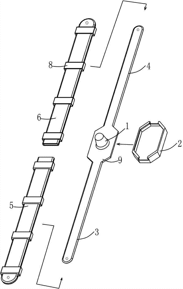
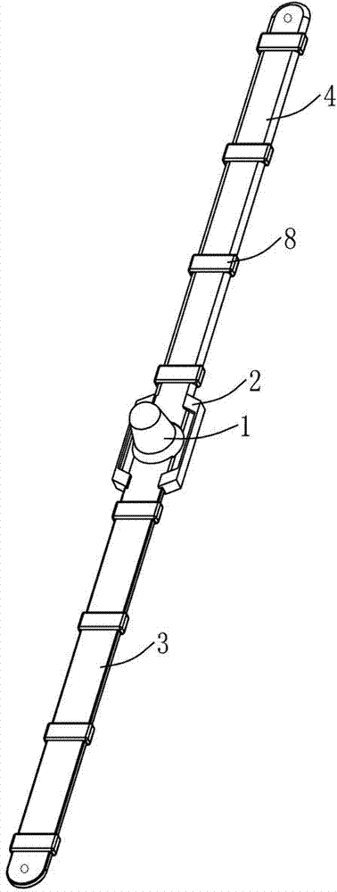
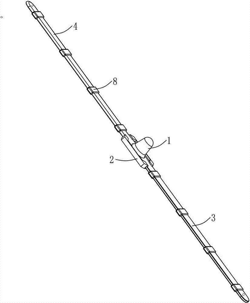
[0027] Embodiment 1: as Figure 1 to Figure 4 As shown, the technical solution adopted by the present invention is as follows: a massage device, characterized in that it includes a massage head 1, a rubber sleeve 2, a first handle 3, a second handle 4 and a connecting plate 9, wherein: the above-mentioned first handle 3 The inner ends of the second handle 4 are respectively fixed on both sides of the connecting plate 9; the above-mentioned massage head 1 is fixed on the connecting plate 9; The second handle cover 6; the above-mentioned rubber cover 2 is set on the outside of the connecting plate 9. When in use, hold the first handle cover 5 and the second handle cover 6, and align the massage head 1 with the massage site for massage.

[0028] The first handle 3 is a sheet-shaped elastic handle, and the first handle cover 5 wrapped outside it is a flexible handle cover. At least two spacer rings 8 are arranged on the outside of the first handle cover 5. The spacer rings 8 will ...

Embodiment 2

[0038] Embodiment 2: as Figure 7 As shown, a massage device is characterized in that it includes a massage head 1, a rubber sleeve 2, a first handle 3, a second handle 4 and a connecting plate 9, wherein: the inner ends of the first handle 3 and the second handle 4 respectively fixed on both sides of the connecting plate 9; the massage head 1 is fixed on the connecting plate 9; the first handle 3 and the second handle 4 are respectively sleeved with a first handle cover 5 and a second handle cover 6; The sleeve 2 is set on the outside of the connecting plate 9, the first handle sleeve 5 and the second handle sleeve 6 run through the two ends of the rubber sleeve 2 respectively, and the outer walls of the two are connected with the inner wall of the rubber sleeve 2 in an interference fit. The handle cover 5 and the second handle cover 6 align the massage head 1 with the massage site for massage.

[0039] Preferably, the first handle 3 is an elastic handle, the first handle 3 ...

Embodiment 3

[0044] Embodiment 3: as Figure 8 As shown, a massage device is characterized in that it includes a massage head 1, a rubber sleeve 2, a first handle 3, a second handle 4 and a connecting plate 9, wherein: the inner ends of the first handle 3 and the second handle 4 respectively fixed on both sides of the connecting plate 9; the massage head 1 is fixed on the connecting plate 9; the first handle 3 and the second handle 4 are respectively sleeved with a first handle cover 5 and a second handle cover 6; The sleeve 2 is set on the outside of the connecting plate 9, the first handle sleeve 5 and the second handle sleeve 6 run through the two ends of the rubber sleeve 2 respectively, and the outer walls of the two are connected with the inner wall of the rubber sleeve 2 in an interference fit. The handle cover 5 and the second handle cover 6 align the massage head 1 with the massage site for massage.

[0045] Preferably, the first handle 3 is an elastic handle, the first handle 3 ...


PUM


Abstract

The invention discloses a massaging device which is characterized in that a massaging head, a rubber sleeve, a first handle, a second handle and a connecting plate are included, wherein the inner ends of the first handle and the second handle are fixed on the two sides of the connecting plate respectively, the massaging head is fixed on the connecting plate, the outer portions of the first handle and the second handle are provided with a first handle sleeve and a second handle sleeve in a sleeved mode respectively, the rubber sleeve is arranged on the outer portion of the connecting plate in a sleeved mode, the first handle sleeve and the second handle sleeve penetrate through the two ends of the rubber sleeve respectively, during using, the first handle sleeve and the second handle sleeve are pressed, and the massaging head is aligned with a massaging portion for massaging. The massaging device can massage the back, the neck, the thighs, the waist and the like of a human body, massaging accuracy is high, a certain part of the body can be massaged stably for a long time in a pointed mode, size is small, weight is light, carrying is convenient, the massaging device can be used in different places, adaptability is high, energy loss is low, and cost is low.

Description

technical field [0001] The invention relates to sports health care equipment, in particular to a massage device. Background technique [0002] The massage device has the effect of promoting local blood circulation and accelerating metabolism on the human body, can relax the body after a day of work, and is beneficial to eliminate fatigue, thus playing a certain fitness effect. Especially for: students, white-collar workers, long-term computer workers; high-level management IT workers; , lower extremity swelling, numbness, poor blood circulation; the frail and old, weakened immunity, etc. The role of massage devices is particularly prominent. [0003] But at present comparatively common massage device generally adopts the mode of electromagnetic vibration, is about to massage device is installed on the back of the chair, the person lies on the seat, starts the massage switch massager to massage the human body, as the Chinese invention patent of application number 20061000944...

Claims


Application Information

Patent Timeline
Patent Type & Authority Patents(China)
IPC IPC(8): A61H15/00
Inventor 黄卓红
Owner 黄卓红
Learn More