Motor-driven electronic hydraulic braking system

A technology of hydraulic braking and motor drive, which is applied in the direction of brakes, brake transmissions, transportation and packaging, etc., can solve the problems of high-pressure accumulator nitrogen leakage, reliability and safety hazards, etc., and achieve fast response speed, Good braking feeling and reduced risk of system failure

Active Publication Date: 2014-04-30
上海同驭汽车科技有限公司
View PDF5 Cites 62 Cited by
  • Summary
  • Abstract
  • Description
  • Claims
  • Application Information

AI Technical Summary

Problems solved by technology

[0005] Most of the current electronic hydraulic braking systems use motors, pumps and high-pressure accumulators as power sources. However, there is a danger of nitrogen leakage in high-pressure accumulators, and there are still hidden dangers in reliability and safety.

Method used


Image

  • Motor-driven electronic hydraulic braking system
  • Motor-driven electronic hydraulic braking system
  • Motor-driven electronic hydraulic braking system

Examples


Embodiment Construction

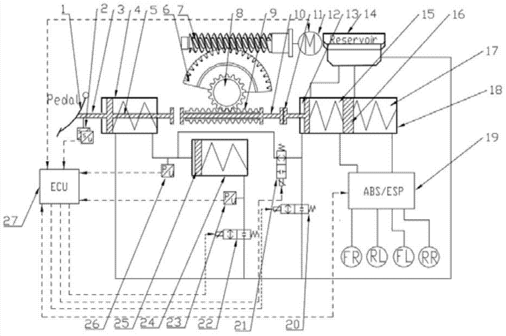
[0035] like figure 1 As shown, the electro-hydraulic braking system driven by a motor mainly includes a brake pedal 1, a secondary master cylinder 3, a pedal simulator 24, a decoupling valve 21, a motor 12, a worm gear 6, a worm screw 7, a master cylinder 18, and a pedal displacement Sensor 2, hydraulic pressure sensor 26, solenoid valves 20, 22.

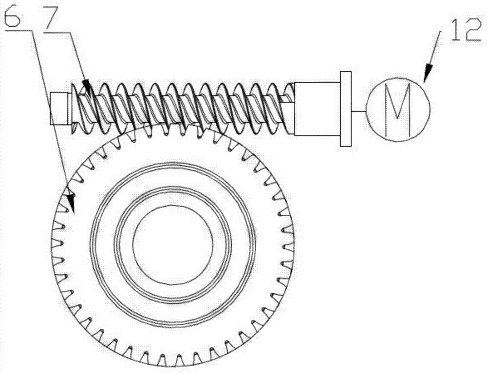
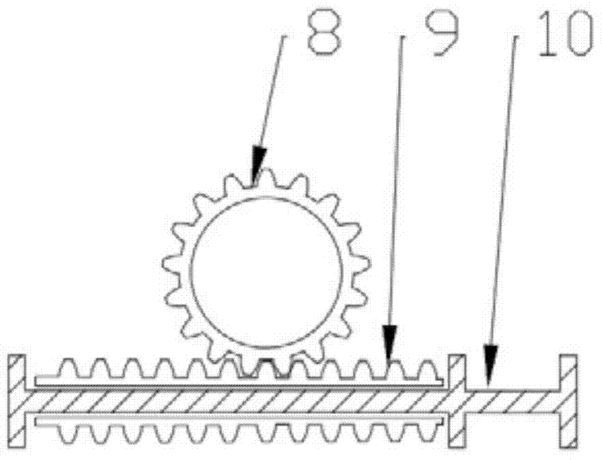
[0036] In this embodiment, the electronically controlled linear motion module includes an electronic control unit ECU27, a motor 12, a reduction mechanism (worm gear 6, worm 7), and a linear motion mechanism (gear 8, rack 9). The motor 12 is connected with the electronic control unit ECU27 through the control circuit, and controls the linear motion mechanism according to the motor torque signal transmitted by the electronic control unit. figure 1 Shown in is a preferred electronically controlled linear motion module, the motor 12 is a rotary motor, the reduction mechanism is a worm gear mechanism, and the linear motion mechanism is...


PUM


Abstract

A motor-driven electronic hydraulic braking system comprises a brake pedal, a pedal displacement sensor, a secondary master cylinder, a pedal simulator pressure sensor, a pedal simulator, pedal simulator solenoid valves, a push rod, an electrically-controlled linear movement module, a brake master cylinder and an ABS/ESP (anti-skid brake system/electronic stability program) module. The electrically-controlled linear movement module drives the push rod to move by means of driving a movement regulating mechanism through a motor, the motor is controlled through a displacement signal, and linear control on braking pressure is realized. The brake master cylinder passes the ABS/ESP module to be hydraulically coupled with vehicle wheel brakes. The ABS/ESP module can passively regulate pressure transmitted from the master cylinder to the wheel brakes, and can actively regulate the pressure of the brake of each wheel. The motor-driven electronic hydraulic braking system has the advantages of rapid response, accurate control on brake fluid pressure, capabilities of well simulating brake pedal feeling of a driver and maximally recovering braking energy, and the like; meanwhile, the system is designed with a dual failure protection mode, thereby having high safety and reliability.

Description

technical field [0001] The invention belongs to the technical field of automobiles, and relates to automobile braking technology, in particular to an electronic hydraulic braking system driven by a motor. Background technique [0002] There are two trends in the development of automobiles today: electrification and intelligence. The electric vehicle is equipped with a high-power drive motor. When the vehicle decelerates and brakes, the motor's drag is used to reverse the power supply to generate a reverse electromotive force, which turns the motor into a generator for power generation, and converts the kinetic energy of the vehicle into electrical energy storage. into the battery, namely regenerative braking (also known as braking energy recovery). These stored electric energy can greatly increase the driving range of the car, and change the disadvantages of low driving range and large battery size of electric vehicles. Today, when the battery technology is not perfect eno...

Claims


Application Information

Patent Timeline
Patent Type & Authority Applications(China)
IPC IPC(8): B60T13/66B60T13/68B60T13/74
Inventor 余卓平广学令徐松云熊璐
Owner 上海同驭汽车科技有限公司
Why Eureka
Try Eureka