
Concrete Slab Concrete Floor Concrete Concrete Concrete Concrete Concrete Construction Method

A technology of frame structure and construction method, applied in construction, building structure, construction material processing and other directions, can solve the problems of high labor intensity of operators, high cost of construction, slow construction progress, etc., to alleviate the pressure of vertical transportation, reduce The effect of rental cost and reduction of lifting times

Active Publication Date: 2017-01-25
芜湖立宇建设有限公司
View PDF3 Cites 0 Cited by
  • Summary
  • Abstract
  • Description
  • Claims
  • Application Information

AI Technical Summary

Problems solved by technology

The core cylinder concrete structure generally adopts the technically more mature climbing formwork construction, while the support system of the outer frame floor of the steel structure is mostly used in two ways, one is the traditional steel pipe full frame plus wooden square plus formwork as the support system The advantage of this method is that it is safe and reliable, but the disadvantage is that the construction progress is slow, the labor intensity of the operator is high, and the cost is high; the other is a profiled steel plate or steel truss floor deck system. The advantages of this construction method are that the construction is convenient and the quality is high. Stable, the disadvantage is that the cost is higher

Method used


Image

  • Concrete Slab Concrete Floor Concrete Concrete Concrete Concrete Concrete Construction Method
  • Concrete Slab Concrete Floor Concrete Concrete Concrete Concrete Concrete Construction Method
  • Concrete Slab Concrete Floor Concrete Concrete Concrete Concrete Concrete Construction Method

Examples


Embodiment Construction

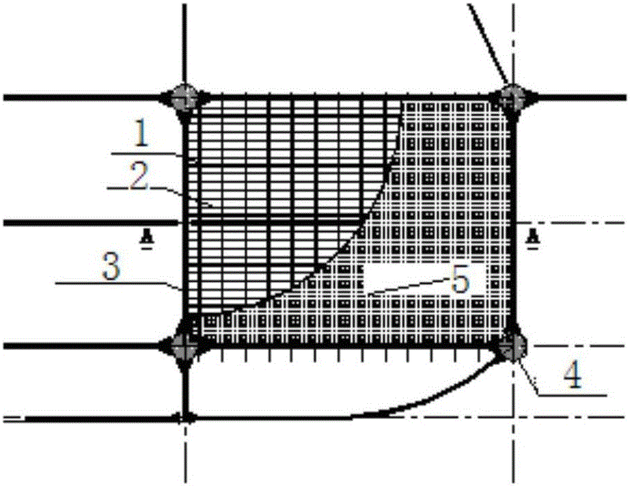
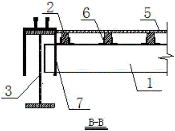
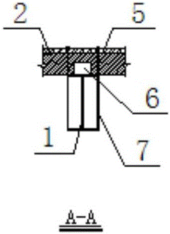
[0053] Below in conjunction with the accompanying drawings, the construction method of the concrete floor slab with steel frame structure will be concretely explained. Among them, in the accompanying drawings, it is marked as main flute 1, secondary flute 2, structural steel beam 3, structural column 4, formwork panel 5, U-shaped fastener 6, and hanger support 7.

[0054] This construction method is suitable for the construction of concrete floor slabs of steel structure concrete floors of high-rise buildings, and the optimal economic and technical spacing of structural steel beams is 2.5m to 5.0m.

[0055] The process principle is to analyze the force of the structural steel beam 3, make full use of the structural steel beam 3 as a supporting system, and use hanging bars to suspend the formwork system on the structural steel beam 3. The formwork system is mainly composed of high-frequency welded I-beams. It consists of corrugated 1 plus wooden side corrugated 2 plus formwork ...


PUM


Abstract

The invention relates to a profile steel framework structure concrete floor slab suspension mould pouring construction method. The profile steel framework structure concrete floor slab suspension mould pouring construction method comprises the steps of installing and correcting profile steel components, measuring a released line, designing and manufacturing a suspension mould system, manufacturing and installing a hoisting bar, installing main rods, installing secondary rods, laying formwork panels, tying floor slab steel bars, pouring and maintaining concrete, and detaching the suspension mould system. Compared with the prior art, the profile steel framework structure concrete floor slab suspension mould pouring construction method has the advantages of being high in construction speed, being stable in quality of a concrete structure, reducing the use of circulation materials, relieving vertical conveying pressure, improving labor efficiency and relieving labor intensity. Compared with a traditional steel pipe whole-building supporting frame, the profile steel framework structure concrete floor slab suspension mould pouring construction method improves the labor efficiency by about 2.5 times. Due to the fact that labor intensity is largely relieved, the work of operators is continuous.

Description

technical field [0001] The invention relates to a construction method, in particular to a construction method for hanging formwork pouring of a steel frame structure concrete floor. Background technique [0002] At present, the structural form of high-rise and super high-rise buildings in my country is mostly reinforced concrete core cylinder plus steel structure outer frame cast-in-place concrete floor. The core cylinder concrete structure generally adopts the technically more mature climbing formwork construction, while the support system of the outer frame floor of the steel structure is mostly used in two ways, one is the traditional steel pipe full frame plus wooden square plus formwork as the support system The advantage of this method is that it is safe and reliable, but the disadvantage is that the construction progress is slow, the labor intensity of the operator is high, and the cost is high; the other is a profiled steel plate or steel truss floor deck system. The...

Claims


Application Information

Patent Timeline
Patent Type & Authority Patents(China)
IPC IPC(8): E04G21/00
Inventor 成军
Owner 芜湖立宇建设有限公司
Learn More