Valve

A valve and spool technology, applied in the field of low-torque and low-friction valves, can solve the problems of spool damage, difficulty in obtaining balanced pre-tightening force, and high precision requirements, so as to achieve safe valve opening and closing, and clear conversion relationship of spool sealing Effect

Active Publication Date: 2014-04-30
SHANGHAI HONGYAN RETURNABLE TRANSIT PACKAGINGS CO LTD
View PDF13 Cites 17 Cited by
  • Summary
  • Abstract
  • Description
  • Claims
  • Application Information

AI Technical Summary

Problems solved by technology

When the valve stem and the rotating disk rotate counterclockwise, under the forced action of the "brace" track on the rotating disk, the limit pin and the sealing structure of the valve first gather toward the center of the fixed disk according to the track of the "straight line" track on the fixed disk. , and then rotate counterclockwise according to the track of the "arc" track on the fixed plate, and the valve opens. The technical disadvantage of this patent is that it uses the track of "arc and straight line", which requires high precision and complicated processing technology. The valve core is a combination It is difficult to obtain a balanced pre-tightening force, resulting in damage to the valve core and shortening the life of the valve
[0006] Chinese patent 200620105067 introduces an orbital plug valve, which includes a valve body, a valve cover, an operating part, a valve stem, a valve seat, a valve plug that forms a conical sealing pair with the valve seat, and an orbital mechanism. The orbital mechanism is installed There is an orbital ring with two guide grooves on the neck of the valve plug and a double-pin plate with two guide pins pinned into the guide grooves. It also includes a lock nut and an adjustment ring to adjust the installation position of the orbital ring. The disadvantages of this patent The structure of the transmission device is complex, which extremely occupies the external space of the valve body; the transmission device involves many parts and the assembly process is complicated
In addition, due to the valve plug of the conical sealing pair, as well as the lock nut and the adjusting ring for adjusting the installation position of the orbital ring, it needs to be adjusted many times, so the operation is complicated

Method used


Image

  • Valve
  • Valve
  • Valve

Examples


Embodiment Construction

[0070] First of all, it should be noted that the specific implementation of the present invention is not limited to the following examples, and those skilled in the art should understand the present invention from the spirit embodied in the following examples, and each technical term can be based on the spirit of the present invention For the broadest understanding, for example, the valve stem is the part used to control the movement of the valve core.

[0071] Preferred embodiments of the present invention will be described in detail below in conjunction with the accompanying drawings. It should be noted that the same or similar components in the drawings are indicated by the same reference numerals; and for the sake of clarity, the related schematic diagrams omit relevant components. Herein, up, down, left, and right directions refer to directions above, below, left, and right viewed from the drawing, unless otherwise specified.

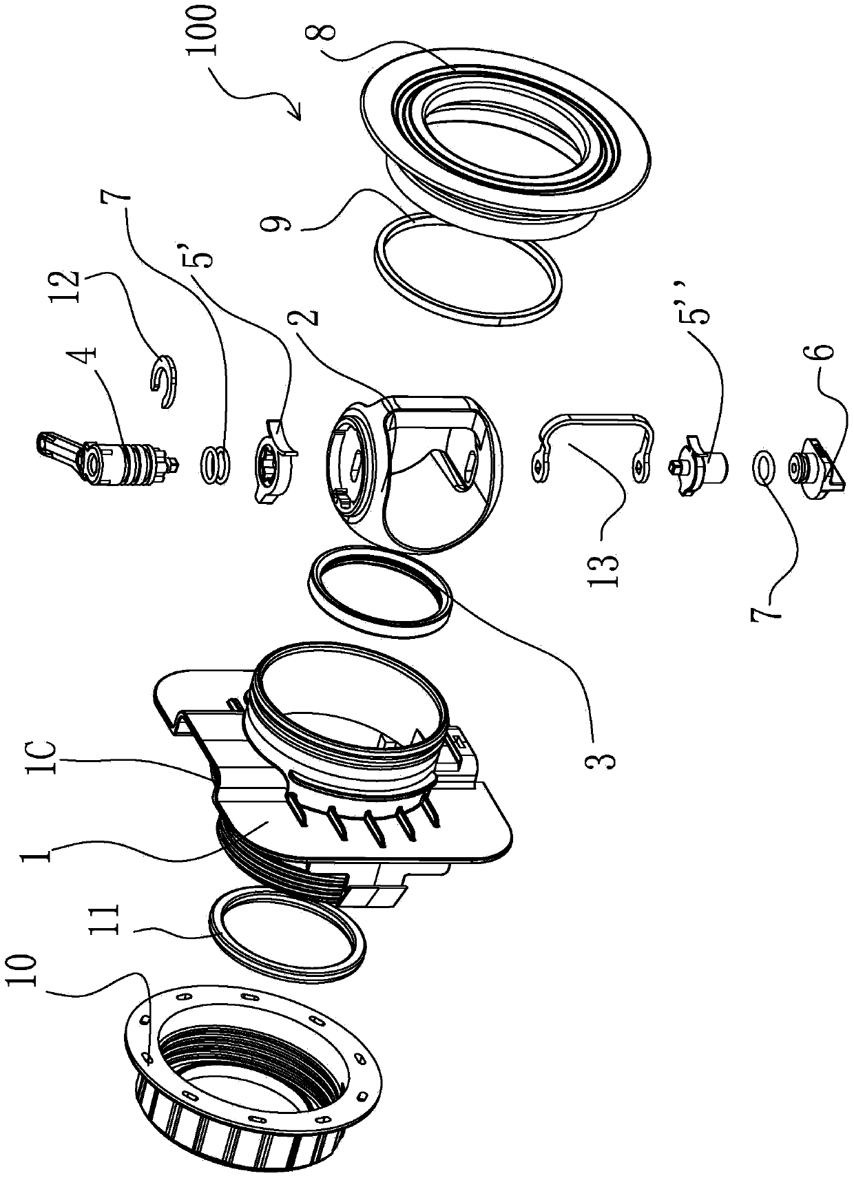
[0072] figure 1 An exploded perspective vi...


PUM


Abstract

The invention discloses a valve. The valve comprises a valve body, a valve rod, a valve element, a vale base, a transmission device and a limiting device. The transmission device is used for transmitting movement of the valve rod to the valve element. The limiting device is used for limiting the movement sequence of the valve element. The valve element is provided with a recess. At least part of the transmission device is disposed in the recess of the valve element, and first transmission and second transmission relationships are formed between the transmission device and the recess of the valve element. The limiting device is used for limiting the movement of the valve element during opening of the valve to enable the transmission device to drive the valve element to do separation movement relative to the valve base before axial rotation of the valve element, and used for not hindering closing of the valve during closing of the valve. The valve can be opened according to a certain movement sequence and is compact in structure and convenient to operate.

Description

technical field [0001] The invention relates to a valve, in particular to a low-torque and low-friction valve. Background technique [0002] In order to optimize the technical parameters of ball valves such as diameter, pressure, torque, and service life, various valve composite opening and closing mechanisms have appeared in recent years. [0003] Chinese patent application number 200720082066 discloses a low-torque ball valve, which provides a low-torque ball valve, including a valve body, a valve ball, a valve seat, a support seat, a valve stem, a driving device, and a valve ball support connection. The disadvantage of this ball valve is that the structure of the driving device is complex, which occupies the outer space of the valve body; the driving device involves many parts and the assembly process is complicated; the opening and closing rotation angle is 180 degrees; The process requirements are very high, and the traditional sealing method and process are easy to ca...

Claims


Application Information

Patent Timeline
Patent Type & Authority Applications(China)
IPC IPC(8): F16K5/06F16K5/08F16K5/20
CPCF16K5/0605F16K5/201F16K27/067F16K5/204F16K5/0647
Inventor 不公告发明人
Owner SHANGHAI HONGYAN RETURNABLE TRANSIT PACKAGINGS CO LTD
Why Eureka
Try Eureka