Coherence optical time domain reflectometer measuring method and reflectometer device

A time-domain reflectometer and time-domain reflectometry technology, which is applied in the field of optical communication, can solve the problems such as the difficulty of reaching spatial resolution below 1 meter, the limited frequency characteristics and noise floor of photoelectric detectors, and the inability to give test results. Achieve ultra-high spatial resolution

Active Publication Date: 2014-04-30
宁波联河光子技术有限公司
View PDF5 Cites 5 Cited by
  • Summary
  • Abstract
  • Description
  • Claims
  • Application Information

AI Technical Summary

Problems solved by technology

[0004] Because the pulse width of OTDR and C-OTDR is limited by the frequency characteristics and noise floor of the photodetector, it is difficult to achieve a spatial resolution of less than 1 meter theoretically.
This technique cannot give accurate test results if adjacent "events" are in close proximity

Method used


Image

  • Coherence optical time domain reflectometer measuring method and reflectometer device
  • Coherence optical time domain reflectometer measuring method and reflectometer device

Examples


Embodiment Construction

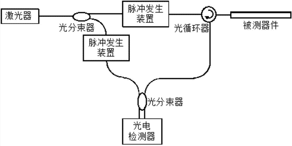
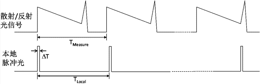
[0012] Such as figure 1 A coherent optical time domain reflectometer device is shown, comprising a laser, an optical beam splitter, a pair of pulse generating devices, an optical circulator, and a photoelectric detector; the laser light generated by the laser is divided into two beams after passing through the optical beam splitter, One is called the test light and the other is called the local light. The two beams of light respectively pass through a pair of pulse generating devices to form a test pulse light and a local pulse light. The test pulse light enters the device under test through the optical beam splitting device (shown as an optical circulator in the figure), where the scattered or reflected optical signal interferes with the local pulse light, and then undergoes photoelectric conversion through the photodetector to obtain the device under test. scatter / reflection information. By adjusting the repetition frequency of the test pulse light and the local pulse ligh...


PUM


Abstract

The invention discloses a coherence optical time domain reflectometer measuring method. The coherence optical time domain reflectometer measuring method is characterized in that test pulsed light is used for acquiring scattering / reflecting information of a device to be measured, local pulsed light and scattered / reflected light signals are used for interference, the scattered / reflected light signals are integrally constructed by adjusting the repetition frequency of the test pulsed light and the repetition frequency of the local pulsed light, the scattering / reflecting light position information is acquired through photovoltaic conversion and analog-digital conversion, the pulse width of the test pulsed light and the pulse width of the local pulsed light adapt to the needed space resolution, and the distance between the adjacent pulses is far larger than the pulse width. A coherence optical time domain reflectometer in which the method is adopted is characterized by comprising a laser, a light beam splitter, a pair of pulse generation devices, a light circulator and a photoelectric detector, the ultrahigh space resolution and the scattering / reflecting light position information can be automatically acquired at the same time, and expensive high-speed photoelectric detectors and expensive high-speed analog-digital converters are not needed.

Description

technical field [0001] The invention relates to the technical field of optical communication, in particular to a coherent optical time-domain reflection measurement method and device. Background technique [0002] Optical Time Domain Reflectometer (OTDR) (Reference 1, M. K. Barnoski, M. D. Rourke, S. M. Jensen, and R. T. Melville, "Optical time domain reflectometer," Appl. Opt. 16, p. 2375 – p. 2379, 1977) , by inputting a light pulse into the device under test, the light signal will return to the starting point of the input after the light pulse is scattered or reflected on the line. By measuring the signal and performing time domain analysis, the state of the line can be obtained, including The basic transmission indicators of the line such as attenuation index, and various "events" on the line such as bending, breaking, and splice loss. The advantage of OTDR technology is long-distance measurement, and the measurable distance can reach 50 kilometers or more. However, it...

Claims


Application Information

Patent Timeline
Patent Type & Authority Applications(China)
IPC IPC(8): H04B10/071
Inventor 樊昕昱何祖源刘庆文杜江兵谢峰马麟
Owner 宁波联河光子技术有限公司
Why Eureka
Try Eureka