Slider for slide fastener

A technology for zippers and sliders, applied in the field of sliders for zippers, which can solve the problems of damage to the elastic sheet, complex structure, and increased cost of the slider 90, and achieve the effect of simplifying the structure

Active Publication Date: 2014-04-30
YKK CORP
View PDF11 Cites 4 Cited by
  • Summary
  • Abstract
  • Description
  • Claims
  • Application Information

AI Technical Summary

Problems solved by technology

Therefore, in the case of manufacturing the slider body 100 having such a structure by die-casting, the structure of the mold is extremely complicated, so there is a problem that the cost of the slider 90 is greatly increased.
[0032] Furthermore, in the slider 70 of Patent Document 1 and the slider 90 of Patent Document 2, when the cover members 71, 91 are attached to the slider main bodies 80, 100, the elastic pieces 73 of the cover members 71, 91, 93 (particularly, the bent portion of the elastic piece 73, 93) is exposed on the front side of the slider main body 80, 100, and for example, when the slider 70, 90 is slid along the engaging direction, the elastic piece 73, 93 is present. Disadvantages of being vulnerable to damage from impact with external parts

Method used


Image

  • Slider for slide fastener
  • Slider for slide fastener
  • Slider for slide fastener

Examples


Embodiment 1

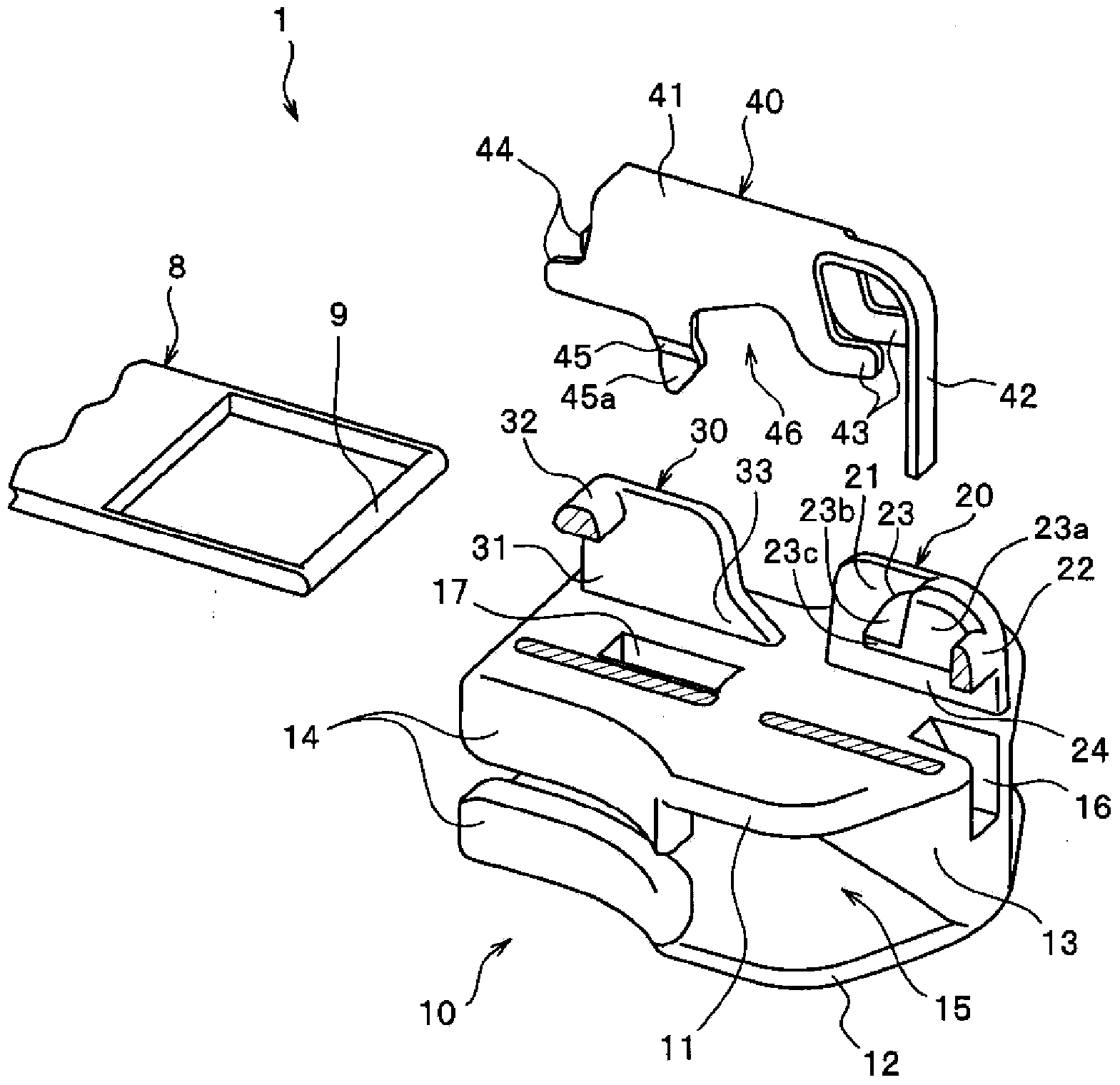
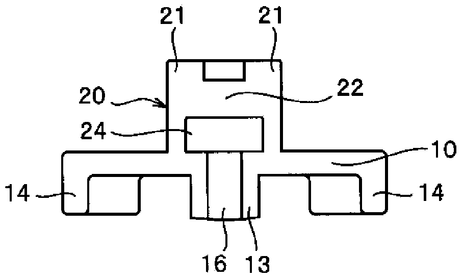
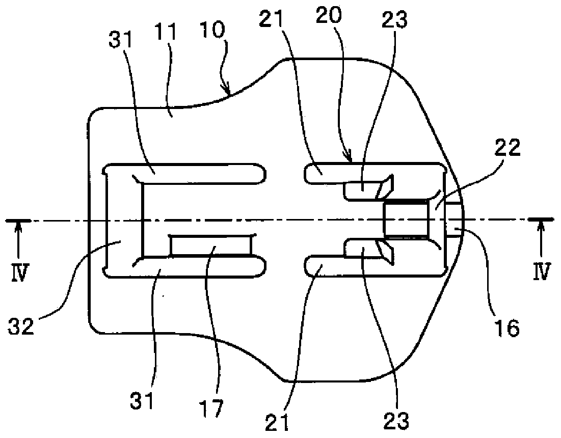
[0133] figure 1 It is an exploded perspective view showing a disassembled state of the slider related to the first embodiment, figure 2 It is an enlarged front view showing the main part of the slider body of the slider. also, image 3 is the top view of the main body of the slider, Figure 4 is along image 3 Sectional view along line IV-IV shown.

[0134] In addition, in figure 1 In order to facilitate understanding of the features of the slider according to the first embodiment, the illustration of the front side wall and the rear side wall of one (right side) of the front mounting portion and the rear mounting portion is omitted. In addition, in Figure 4 In , in order to clearly show the position of the stop claw disposed on the right side wall of the cover member, the stop claw that is not actually shown in this cross-sectional view is indicated by a dotted line.

[0135]In addition, in the following description, the front-rear direction of the slider refers to...

Embodiment 2

[0194] Figure 12 It is a sectional view showing the slider related to the second embodiment, Figure 13 It is a side view which shows the cover of this slider.

[0195] In addition, in the present embodiment 2 and the later-described embodiment 3, the structure different from that of the slider 1 related to the above-mentioned embodiment 1 will be mainly described, and the structures related to the above-mentioned embodiment 1 will be denoted by using the same reference numerals. The components or members of the slider 1 have substantially the same structure, and their descriptions are omitted.

[0196] The slider 2 according to the second embodiment includes: a slider main body 10a, a handle 8 having an installation shaft 9 , and a cover member 40a, and a downward-facing hook is disposed on the front end of the locking piece 43 of the cover member 40a. The engaging portion 47 is in a curved form.

[0197] In addition, on the upper blade 11a of the slider main body 10a, an...

Embodiment 3

[0201] Figure 14 It is a schematic diagram showing the slider main body and the cover member constituting the slider according to the third embodiment, Figure 15 is an enlarged view of main parts showing main parts of the slider. In addition, in Figure 14 In order to easily determine the characteristics of the slider according to the third embodiment, the slider main body is shown in cross-sectional view, and the cover member is shown in side view.

[0202] The slider 3 according to the third embodiment includes a slider main body 50 , a handle 8 having an attachment shaft portion 9 , and a cover member 60 .

[0203] The cover member 60 includes: a cover main body 61 with an inverted U-shaped cross section; a sheet-shaped elastic piece 62 extending from the front end of the upper surface of the cover main body 61; The extended locking piece 63; the protruding piece 64 protruding rearward from the lower end of the left and right side walls of the cover main body 61; The ...


PUM


Abstract

This slider (1, 2, 3) has: a slider body (10, 10a, 50) provided with first and second mounting sections (20, 30); a pull tab (8); and a cover member (40, 40a, 60). The cover member (40, 40a, 60) is provided with: latch sections (43, 63) extending forward from the cover body (41, 61); and a stop claw section (45, 65). The first mounting section (20) is provided with: left and right first side wall bodies (21); a first connection bar (22) for connecting the first side wall bodies (21); and a housing space (24) disposed between the first connection bar (22) and an upper wing plate (11, 11a, 51) and housing the latch sections (43, 63). The housing space (24) penetrates through the first mounting section (20) in the length direction of the slider. As a result of the configuration, the manufacturing cost of the slider (1, 2, 3) is reduced, the first mounting section (20) can be reinforced by the first connection bar (22), and an elastic section (42, 62) can be protected.

Description

technical field [0001] The present invention relates to a slider for a slide fastener having a stop mechanism, and particularly relates to a slider configured by covering an attachment shaft portion of a handle with a cover member and attaching the cover member to a slider main body. Background technique [0002] As sliders used for slide fasteners, various types of sliders are conventionally used. As one of these many sliders, it is known that the cover member can be assembled to the slider main body with the handle sandwiched between the cover member and the slider main body, thereby completing the attachment of the handle. As for the slider, examples of such a slider are disclosed in, for example, JP-A-2007-111351 (Patent Document 1) and JP-A-7-21123 (Patent Document 2). [0003] Such as Figure 16 As shown, the slider 70 described in Patent Document 1 includes a slider body 80 , a handle 78 having an attachment shaft portion (pivot) 79 , and a cover member 71 attached t...

Claims


Application Information

Patent Timeline
IPC IPC(8): A44B19/30
CPCA44B19/306
Inventor 濱田嘉一槻慶一
Owner YKK CORP
Why Eureka
Try Eureka