


Quick Research
Generate reliable direction feasibility study reports for your R&D in just a few steps.

Technical Q&A
Discover and master advanced knowledge NOW. Basics, ideas, possibilities, all at once.

Find Solutions
As an expert in R&D theories, this can generate solutions to your technical problems instantly.

Evaluate Feasibility
Analyze your overall solution with one click, know your potential R&D risks in advance.

Monitor Landscape
Get weekly tech updates, stay abreast of the latest tech innovations and key insights.
Cooled magnet motor
A technology of motors and electric motors, applied in cooling/ventilation devices, magnetic circuit rotating parts, magnetic circuit shape/style/structure, etc., can solve problems such as winding heat and increasing winding resistance
- Summary
- Abstract
- Description
- Claims
- Application Information
AI Technical Summary
Problems solved by technology
Method used
Image

Examples
Embodiment Construction
[0043] Hereinafter, a detailed description of the present invention will be given. It will be appreciated that these figures are for illustration purposes only and do not limit the scope of the invention in any way.
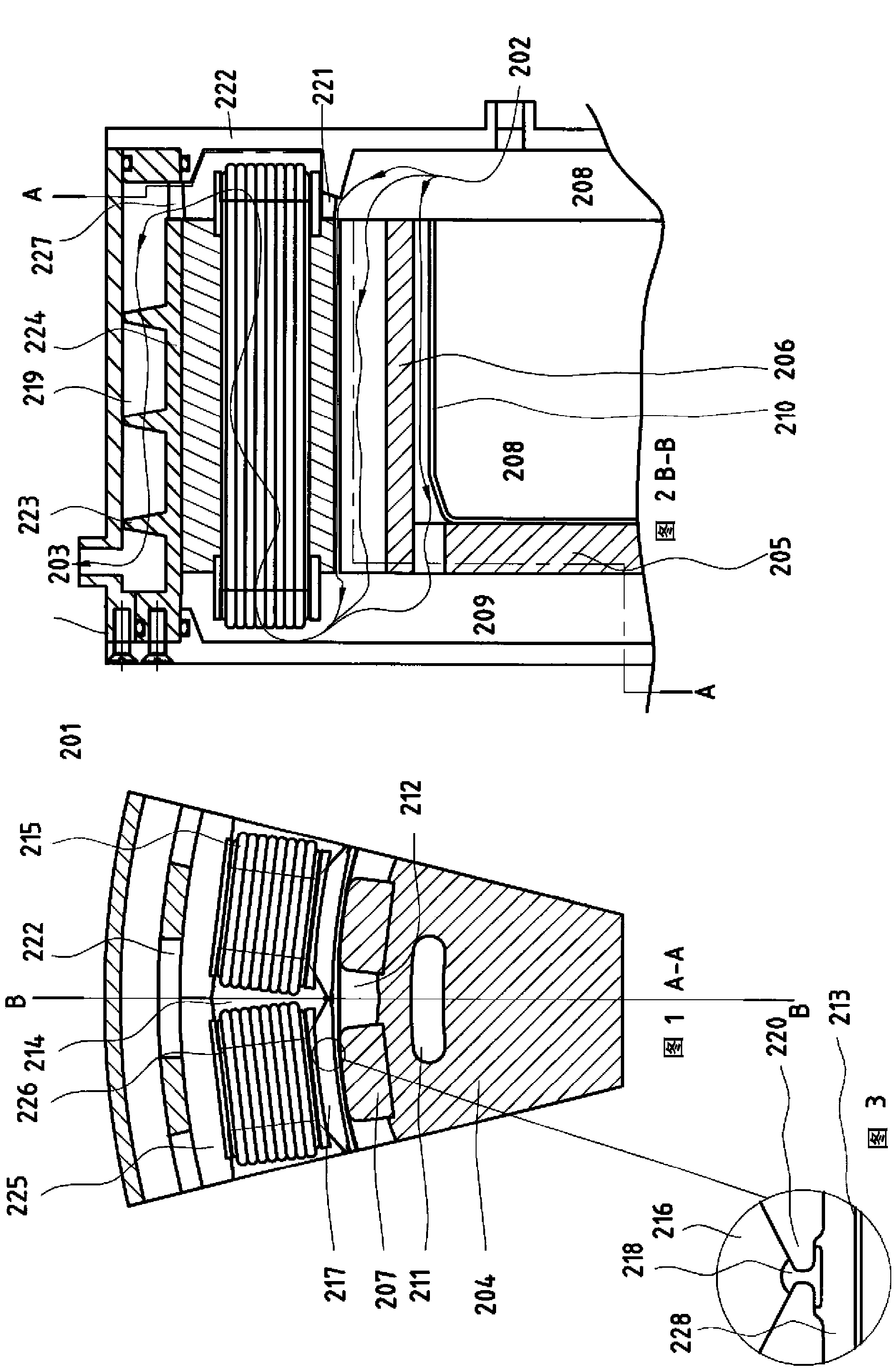
[0044] figure 1 shown with the figure 2 Shown in section A-A perpendicular to the axis of the motor or generator.
[0045] figure 2 Section B-B parallel to the axis of the same permanent magnet motor / generator 201 is shown. Magnets have a very high magnetic energy product (BH product), but are limited in their ability to withstand high stator currents at high temperatures. Cooling of the magnets is performed by a flow of cooling fluid which, after entering the motor / generator, is directed to the rotor magnet channels through paths (202-208) which do not cause any substantial heating of the fluid.
[0046] The fluid follows the path indicated by the thin lines from 202 to 203 . The rotor 204 has a disk portion 205 and a hollow cylindrical portion 206 on w...
PUM
 Abstract
Description
Claims
Application Information
 - R&D Engineer
- R&D Manager
- IP Professional
- Industry Leading Data Capabilities
- Powerful AI technology
- Patent DNA Extraction
Browse by: Latest US Patents, China's latest patents, Technical Efficacy Thesaurus, Application Domain, Technology Topic, Popular Technical Reports.
© 2024 PatSnap. All rights reserved.Legal|Privacy policy|Modern Slavery Act Transparency Statement|Sitemap|About US| Contact US: help@patsnap.com