Particle ray irradiating device

An irradiation device and particle beam technology, applied in the directions of X-ray/γ-ray/particle irradiation therapy, etc., can solve the problems of wrong irradiation, residual magnetic field, beam irradiation position shift, etc., and achieve the effect of improving accuracy

Active Publication Date: 2014-05-07
HITACHI LTD
View PDF9 Cites 5 Cited by
  • Summary
  • Abstract
  • Description
  • Claims
  • Application Information

AI Technical Summary

Problems solved by technology

However, the set current value of the scanning electromagnet calculated by this theoretical formula is a theoretical value obtained on the premise that the specifications of the scanning electromagnet, the scanning power supply, and the specification of the irradiation particle beam are completely unchanged. However, due to In reality, it will change due to various reasons, so the irradiation position may be shifted, resulting in wrong irradiation
[0004] For

Method used


Image

  • Particle ray irradiating device
  • Particle ray irradiating device
  • Particle ray irradiating device

Examples


Embodiment approach 1

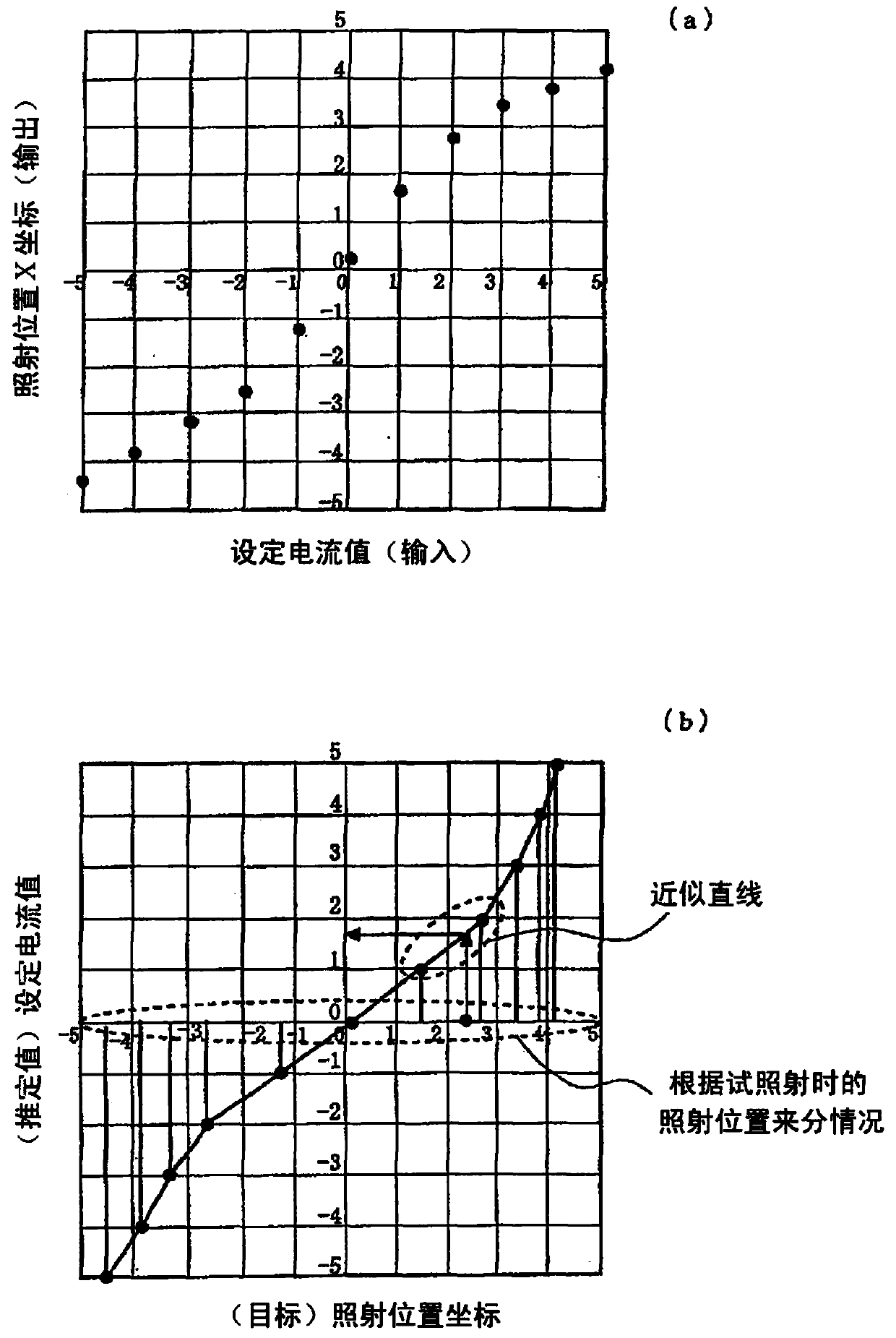
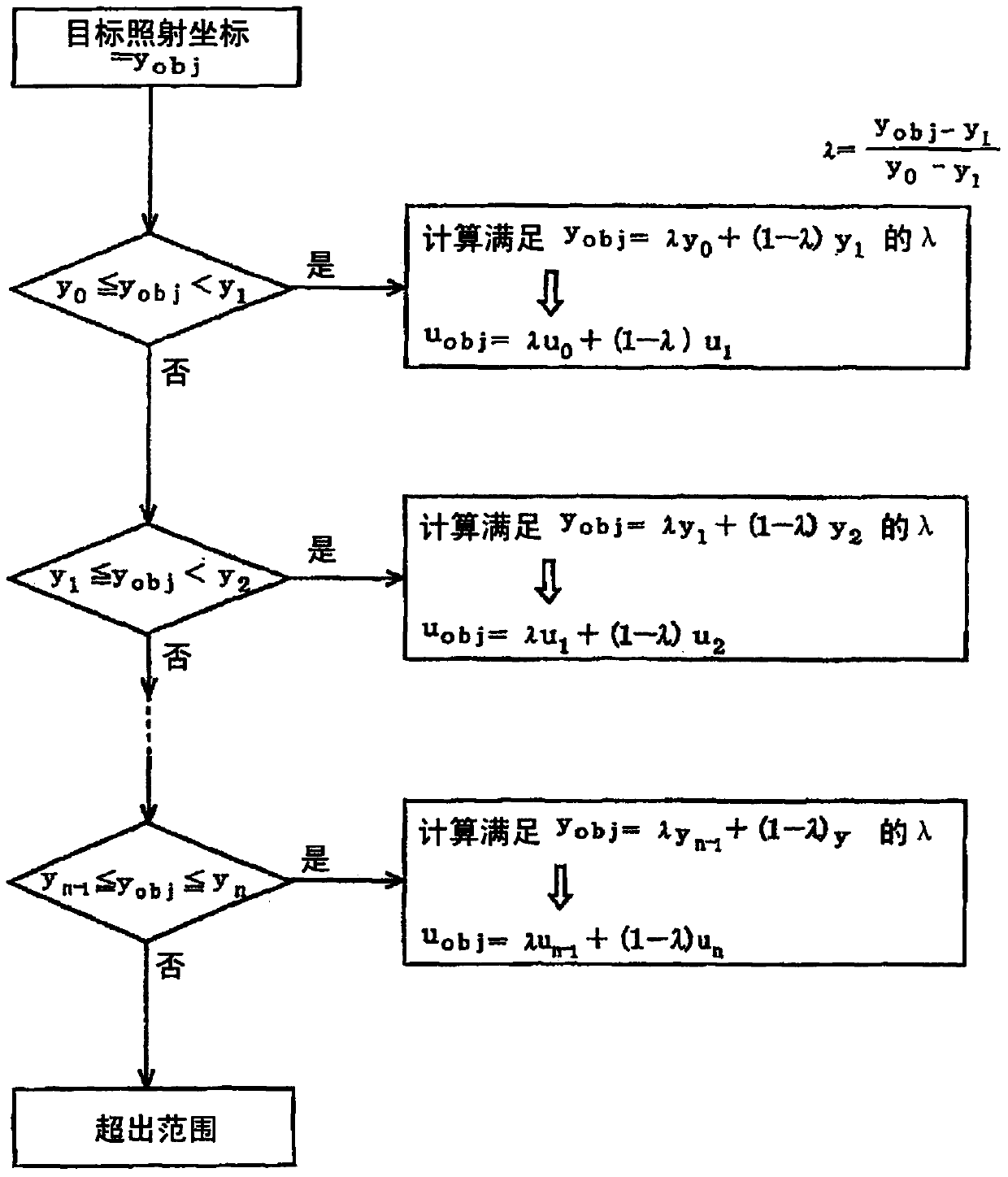
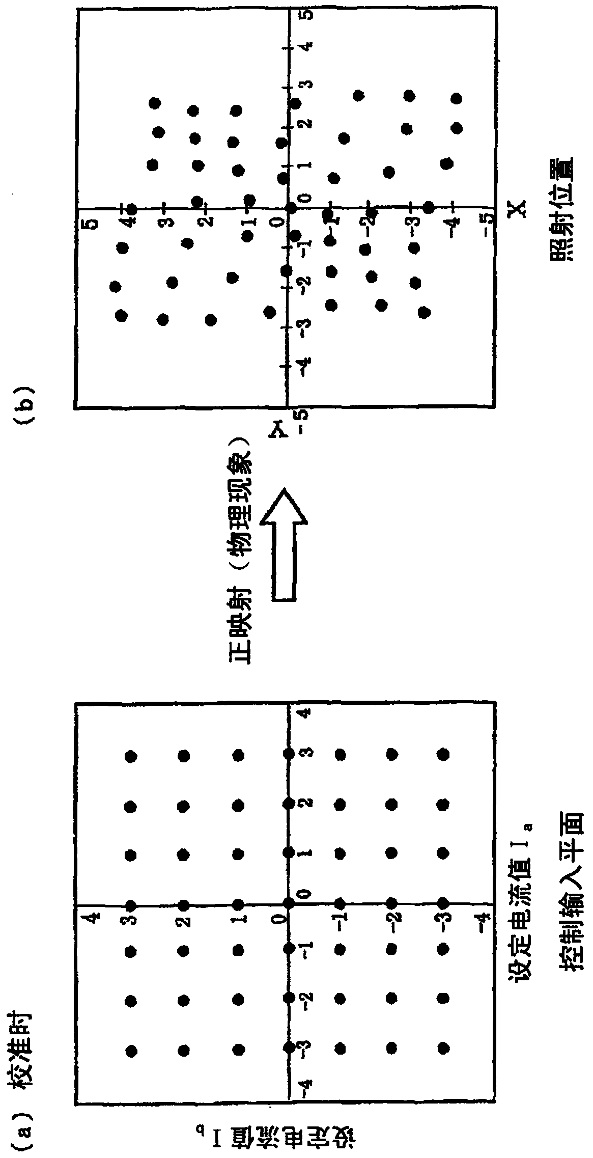
[0079] Image 6 It is a configuration diagram showing a particle beam irradiation apparatus for scanning irradiation in Embodiment 1 of the present invention. The particle ray irradiation device includes: an accelerator 11, which accelerates the charged particle beam 1 into a charged particle beam 1 with desired kinetic energy; a beam conveying pipe 2, which conveys the charged particle beam 1; scanning electromagnetic Iron 3, the scanning electromagnet 3 scans the charged particle beam 1; the beam exit window 4, the beam exit window 4 emits the beam; and a scanning controller 10, the scanning controller 10 sends instructions to the scanning electromagnet 3 value. In the beam conveying system with the beam conveying pipeline 2 , deflection electromagnets, beam monitors, shielding electromagnets, beam dampers (beam dampers), irradiation route deflection electromagnets and the like are provided. The particle beam irradiation apparatus according to Embodiment 1 has, in the scan...

Embodiment approach 2

[0112] Figure 11 It is a configuration diagram showing a particle beam irradiation device in Embodiment 2. In Embodiment 1, the inverse mapping mathematical model is set as two inputs and two outputs, but in Embodiment 2, such as Figure 11 , Mathematical Formula 11 (described later), the inverse mapping mathematical model is set to three inputs and three outputs. The following Mathematical Expression 11 shows a polynomial model composed of target irradiation position coordinates in the case of three inputs and three outputs, and the highest order is two.

[0113] [mathematical formula 11]

[0114] I ae = a 000 + a 001 x + a 002 ...

Embodiment approach 3

[0137] Figure 12 It is a block diagram showing the particle beam therapy apparatus in Embodiment 3. 31 is the last deflection electromagnet installed in the beam delivery system, which is arranged upstream of the scanning electromagnet 3b in the Y direction, and deflects the charged particle beam to paths A, B, and C. In Embodiment 1 of Image 6 In , the simple case where the scanning electromagnet 3 is located at the most downstream is shown, and the case where a deflection electromagnet is provided downstream of the scanning electromagnet (swing electromagnet) and the scanning electromagnet is omitted by making better use of the deflection electromagnet are omitted. The case of the electromagnet. The present invention can also be applied to the above-mentioned structural example, or in the case of adopting the above-mentioned structure, since the forward mapping from the command value coordinate space 6 to the beam irradiation position coordinate space 7 becomes more comp...


PUM


Abstract

The invention aims to provide a particle ray irradiating device. The particle ray irradiating device can calculate control instruction values and improve irradiating position accuracy without using IF conditional sentences (conditional expressions for differentiating conditions). The particle ray irradiating device comprises an inverse mapping unit, wherein the inverse mapping unit is provided with an inverse mapping mathematic model which generates instruction values, for achieving irradiation, of a scanning electromagnet based on target irradiating position coordinates of charged particle beams of an irradiated objective, and according to the instruction values generated by using the inverse mapping mathematic model based on the target irradiating position coordinates of the charged particle beams of the irradiated objective, the scanning electromagnet is controlled to scan the charged particle beams to irradiate the charged particle beams to the irradiated objective.

Description

[0001] This application is a divisional application of an invention patent application named "Particle Beam Irradiation Device", with an international filing date of June 9, 2009, and application number 200980159044.6 (international application number is PCT / JP2009 / 060531). technical field [0002] The present invention relates to a particle beam irradiation device used for medical treatment or research such as cancer treatment. In particular, it relates to a particle beam irradiation device for performing scanning irradiation such as spot scanning and raster scanning. Background technique [0003] In a conventional particle beam irradiation apparatus that performs scanning irradiation, as disclosed in Patent Document 1, in order to scan a charged particle beam, the set current of a scanning electromagnet that is a scanning unit is changed over time. The set current value of the scanning electromagnet can be obtained by a theoretical formula based on the specifications of th...

Claims


Application Information

Patent Timeline
IPC IPC(8): A61N5/10
Inventor 岩田高明
Owner HITACHI LTD
Why Eureka
Try Eureka