Gap-adjustable rolling slide composite guide rail pair

An adjustable, guide rail pair technology, applied in the field of guide rail pairs, can solve the problems of difficult to meet the performance index and accuracy requirements of heavy machine tools, large contact area of ​​sliding guide rails, poor vibration resistance, poor rigidity, etc. Performance, uniform force effect

Active Publication Date: 2014-05-07
NANJING UNIV OF SCI & TECH
View PDF7 Cites 7 Cited by
  • Summary
  • Abstract
  • Description
  • Claims
  • Application Information

AI Technical Summary

Problems solved by technology

[0004] The rolling guide rail is made of rolling elements placed between the guide part and the moving part, and can make the matching two guide rail surfaces not directly contact, so it has small frictional resistance, good follow-up and high-speed motion performance, positioning accuracy and repeatability It has the advantages of high positioning accuracy, but its contact stress is large under heavy load, and its vibration resistance and rigidity are poor.
[0005] The sliding guide rail has a large contact area, and most of them use inlaid guide rails or plastic-coated guide rails. They have large bearing capacity, good vibration resistance and rigidity, but their dynamic and static friction is relatively large, and their movement sensitivity is low. They are easy to "crawl" and wear at low speeds. , the disadvantage of short service life
[0006] The hydrostatic guideway adopts liquid friction, and the oil film has good vibration resistance, but its structure is complicated, the cost is high, and maintenance is difficult, so it has not been widely used.
[0007] The above types of guide rails have their own advantages and disadvantages. It is difficult to achieve the ideal performance index and accuracy requirements of heavy-duty machine tools if rolling guide rails or sliding guide rails are used alone.

Method used


Image

  • Gap-adjustable rolling slide composite guide rail pair
  • Gap-adjustable rolling slide composite guide rail pair
  • Gap-adjustable rolling slide composite guide rail pair

Examples


Embodiment Construction

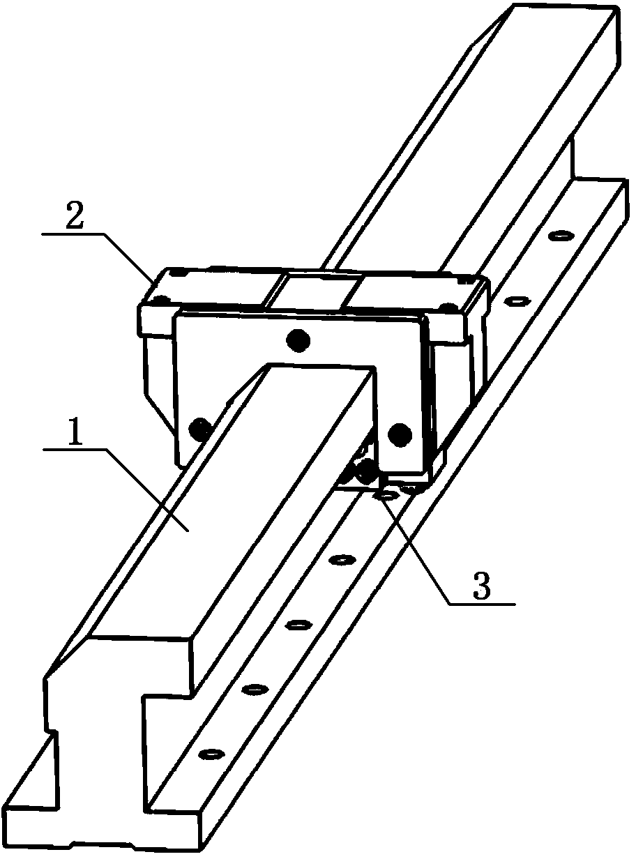
[0021] combine Figure 1 to Figure 5 , a gap-adjustable rolling-sliding composite guide rail pair, including a guide rail 1, a slider 2 and a gap adjustment mechanism 3, the slider 2 is arranged on the guide rail 1, and the gap adjustment mechanism 3 is located between the guide rail 1 and the slider 2,

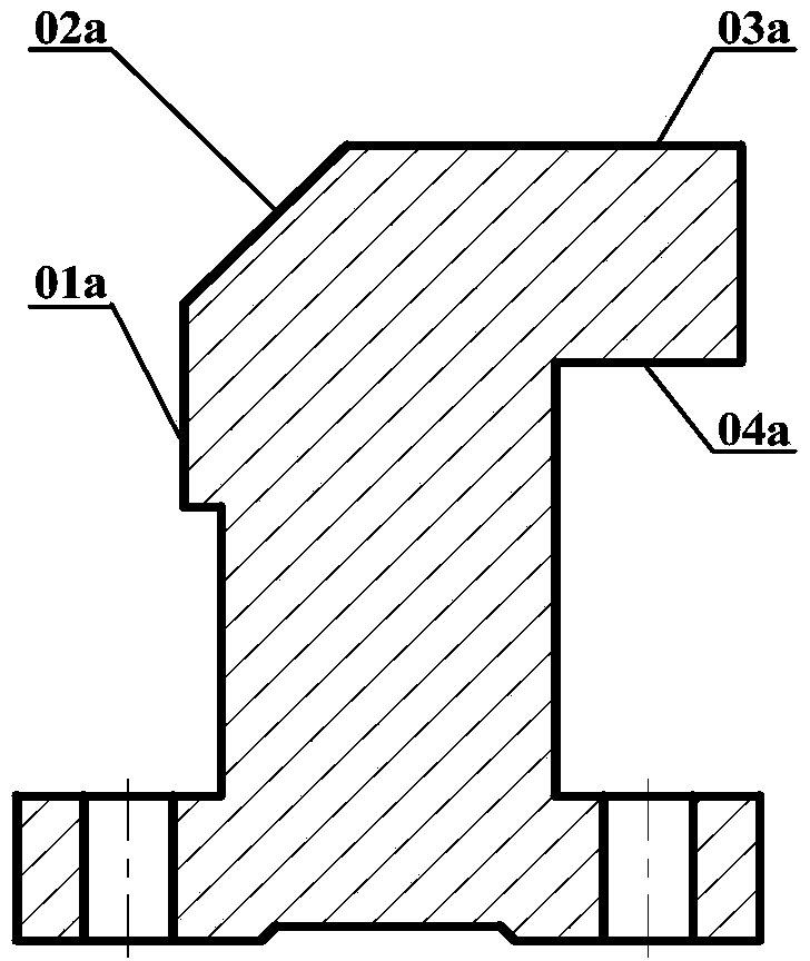
[0022] The left side 01a of the guide rail is a lateral bearing surface, the upper left corner of the guide rail is an inclined surface 02a, the inclined surface is a guiding surface, the upper surface 03a of the guide rail is a normal bearing surface, and the lower surface 04a of the right raised portion of the guide rail is a preload bearing surface;

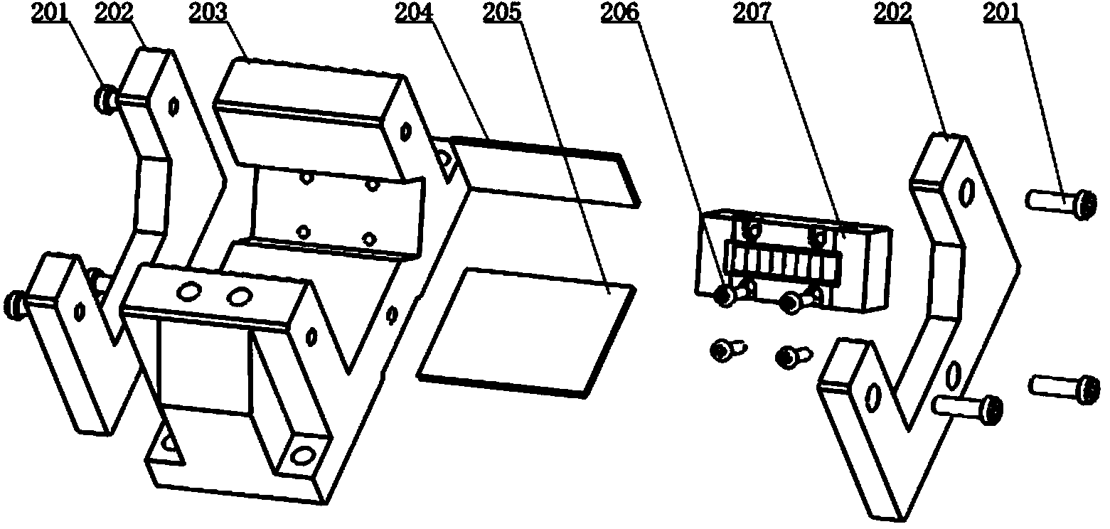
[0023] The slider 2 includes two end baffles 202 and a slider body 203. The two end baffles 202 are located on the front and rear sides of the slider body 203. The bottom of the slider is provided with a groove that matches the guide rail. A first guide rail soft belt 204 is arranged along the length direction of the guide ra...


PUM


Abstract

The invention discloses a gap-adjustable rolling slide composite guide rail pair. The gap-adjustable rolling slide composite guide rail pair comprises a guide rail, a slider and a gas adjusting mechanism which are in mutual match; the slider comprises two end surface baffles and a slider body; a groove matched with the guide rail is arranged at the bottom of the slider; a guide rail soft belt is arranged between the left side surface of the groove and the lateral carrying surface of the guide rail along the length direction of the guide rail; a guide rail soft belt is arranged between the upper surface of the groove and the normal carrying surface of the guide rail along the length direction of the guide rail; a U-shaped slot is arranged at the left lower corner of the groove; a rolling block matched with the guide surface of the guide rail is arranged in the U-shaped slot along the length direction of the guide rail. The gap-adjustable rolling slide composite guide rail pair integrates the advantages of a rolling guide rail and a slide rail, the guide and positioning precision and the carrying capacity of the guide rail are ensured under the heavy load and heavy cutting conditions, the motion resistance is reasonably effectively reduced, the sensitivity, rigidity and vibration resistance of the motion guide rail are improved, the machining efficiency is improved, and the service life of the guide rail is prolonged.

Description

technical field [0001] The invention belongs to the technical field of guide rail pairs, in particular to a sliding composite guide rail pair with adjustable clearance. Background technique [0002] With the rapid development of China's economy, large-scale projects such as high-speed railways, wind power equipment, domestic large aircraft projects, aerospace equipment, automobile manufacturing equipment and engineering machinery manufacturing have performance requirements for heavy-duty CNC machine tools that can achieve heavy-duty, high-speed and high-torque cutting increasing day by day. Guide rail is one of the core components of heavy-duty CNC machine tools, which largely determines the rigidity, accuracy and precision retention of heavy-duty CNC machine tools. The executive components (spindle box, tool holder, workbench) of heavy-duty CNC machine tools are heavy, which puts forward higher requirements for the bearing capacity of the guide rail and the motion performa...

Claims


Application Information

Patent Timeline
Patent Type & Authority Applications(China)
IPC IPC(8): B23Q1/01
CPCB23Q1/017
Inventor 汪振华杨尧袁军堂程寓胡小秋
Owner NANJING UNIV OF SCI & TECH
Why Eureka
Try Eureka