Method and device for synchronously lifting steel reinforcement cage

A steel cage and equipment technology, applied in the direction of ceramic molding machines, manufacturing tools, etc., can solve the problems of unstable operation, high operating cost, cumbersome operation, etc., and achieve the effects of stable operation, pollution avoidance and cost saving

Active Publication Date: 2014-05-07
CCCC FOURTH HARBOR ENG CO LTD +3
View PDF7 Cites 3 Cited by
  • Summary
  • Abstract
  • Description
  • Claims
  • Application Information

AI Technical Summary

Problems solved by technology

The existing equipment in the pouring area lifts the large pipe section steel cage to complete the force conversion, the structure is complex, the operation is cumbersome, and the operation is not stable enough, and the operation cost is high

Method used


Image

  • Method and device for synchronously lifting steel reinforcement cage
  • Method and device for synchronously lifting steel reinforcement cage
  • Method and device for synchronously lifting steel reinforcement cage

Examples


Embodiment Construction

[0031] The specific implementation manner of the present invention will be described in detail below in conjunction with the accompanying drawings.

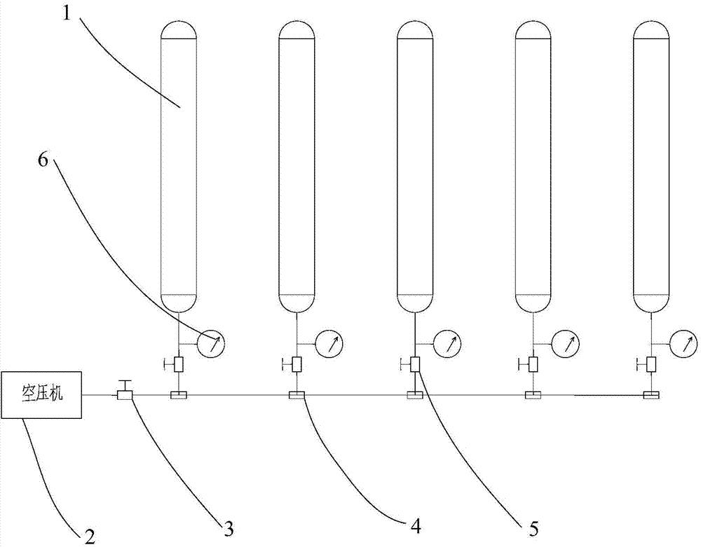
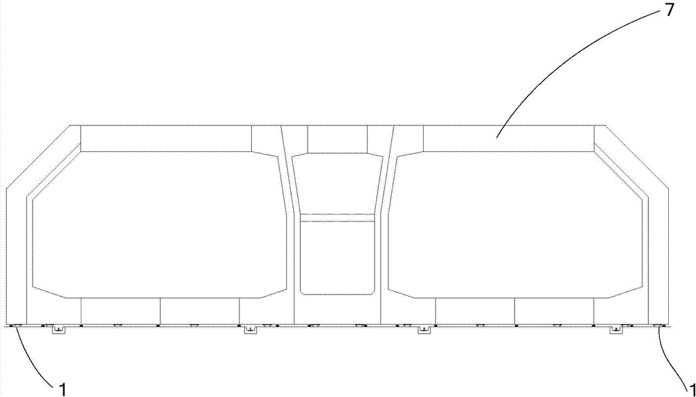
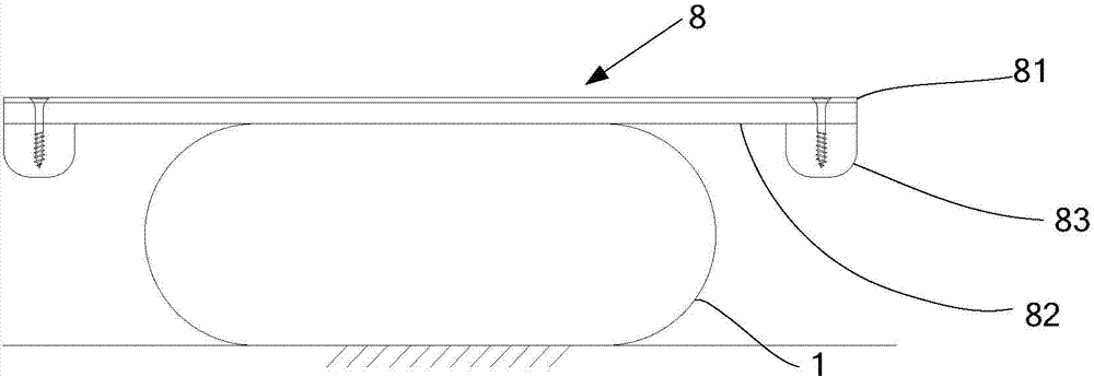
[0032] Such as figure 1 , image 3 As shown, this implementation provides a synchronous lifting reinforcement cage equipment in the process of manufacturing tunnel immersed tubes, and the equipment adopts the airbag jacking method. The device comprises a plurality of airbags 1 , an airbag backing plate 8 and an air compressor 2 , the airbag backing plate is arranged on the upper surface of the plurality of airbags, and the air compressor communicates with the plurality of airbags through pipelines. Such as figure 2 As shown, the airbag is in contact with the bottom of the reinforcement cage 7 through the airbag backing plate to increase the lifting contact area. The pipeline includes a trachea main circuit, and the trachea main circuit is provided with a plurality of trachea branches, and the trachea main circuit is connected...


PUM


Abstract

The invention relates to the manufacturing field of undersea tunnel immersed tubes, in particular to a device and method for synchronously lifting a steel reinforcement cage in the tunnel immersed tube manufacturing process. The device comprises a plurality of air sacs, air sac base plates and an air compressor, the air sac base plates are arranged on the upper surfaces of the air sacs, and the air compressor is respectively communicated with the air sacs thorough pipes. The method includes the steps that firstly, after the steel reinforcement cage is pushed by a sliding rail to be in place, the air sacs with the air sac base plates are installed on the lower portion of the steel reinforcement cage; then air is inflated into the air sacs by the air compressor through the pipes, and when the steel reinforcement cage is lifted to reach the set height, air inflation is stopped; finally, after the sliding rail is disassembled, the air sacs slowly exhaust air through an air exhaust valve, a supporting column arranged on the air sac base plates is stressed, and then the air sacs are taken out. According to the device and method for synchronously lifting the steel reinforcement cage, the air sacs are inflated to lift the steel reinforcement cage, the steel reinforcement cage stably operates, and the height of the steel reinforcement cage can be accurately controlled. The device is simple in structure, and cost can be saved compared with existing hydraulic and pneumatic mechanical devices.

Description

technical field [0001] The invention relates to the field of manufacturing subsea tunnel immersed tubes, in particular to a method and equipment for synchronously lifting reinforcement cages in the process of manufacturing tunnel immersed tubes. Background technique [0002] At present, there are multiple pipe joints in the immersed pipe of the subsea tunnel of the cross-sea bridge, and the production line is set up to prefabricate the pipe joints. The pipe joint prefabrication plant has multiple production lines, each production line includes a steel bar binding pedestal and a pouring pedestal, and the steel bar binding pedestal is sequentially bound to the bottom plate steel bar, the partition wall side wall steel bar, and the roof plate steel bar. [0003] The pushing process of the steel cage of the pipe section is as follows: first complete the binding of the steel bars on the bottom plate, then move it longitudinally to the preset station through the steel cage pushing...

Claims


Application Information

Patent Timeline
Patent Type & Authority Applications(China)
IPC IPC(8): B28B23/02
CPCB28B23/022
Inventor 梁杰忠陈伟彬张文森董政申昌洲
Owner CCCC FOURTH HARBOR ENG CO LTD
Why Eureka
Try Eureka