Groove type machine barrel extruding machine
An extruder and barrel technology, applied in the field of grooved barrel extruders, can solve the problems of high energy consumption and low melting and plasticizing efficiency, and achieve the advantages of low energy consumption, improved melting efficiency and high extrusion output. Effect
- Summary
- Abstract
- Description
- Claims
- Application Information
AI Technical Summary
Problems solved by technology
Method used
Image
Examples
no. 1 example
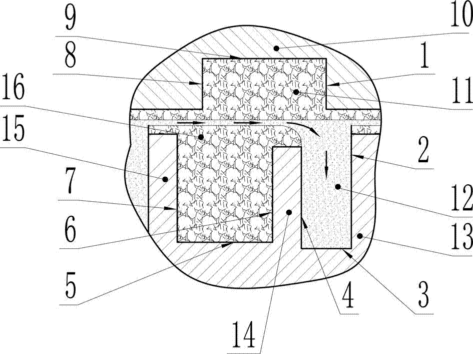
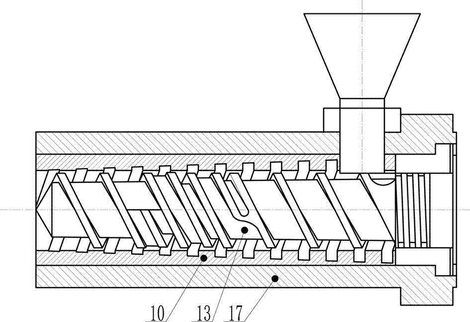
[0024] The first embodiment: the outer surface of the screw and the inner surface of the barrel bushing are both cylindrical, the diameter of the screw is D=90mm, the lead is 90mm, the number of threads is 1, the aspect ratio is 30, right-handed, and the main flight The width is 7.2mm, the groove depth of the solid conveying section is 5.0mm, and the length is 7.5D. The groove depth of the melt conveying section is 13.9mm, and the length is 17.5D. At the end of the section, there is a secondary thread, the width of the secondary thread is 5.4mm, the width of the separated solid-phase screw groove is 46.0mm, the depth of the solid-phase screw groove is reduced from 6.0mm to 0mm, and the width of the liquid-phase screw groove is 22.4mm. The groove depth is increased from 20.2mm to 30.0mm; the inner diameter of the barrel bushing is 90.5mm, the number of grooves is 12, left-handed, the groove thread rise angle is 51.8°, and the groove depth at the initial end of the solid conveying ...
no. 2 example
[0027] The second embodiment: the outer surface of the example screw and the inner surface of the barrel bushing are both cylindrical, the diameter of the screw is D=90mm, the lead is 90mm, the number of threads is 1, the aspect ratio is 25, right-handed, solid conveying The depth of the section screw groove is 6.0mm, and the length is 8D; the depth of the screw groove in the melt conveying section is 15.3mm, and the length is 7D; the melting section is a separate screw, and the length is 10D; the end of the solid conveying section has a secondary thread, and the width of the secondary thread is 7.2 mm, the depth of the separated solid-phase screw groove is 6.0mm, and the depth of the liquid-phase screw groove is 15.3mm; the inner diameter of the barrel bushing is 90.5mm, the number of grooves is 10, left-handed, and the lead angle of the groove is 46.7°, the groove depth of the solid conveying section of the barrel bush groove is 5.0mm, the initial groove depth of the barrel b...
no. 3 example
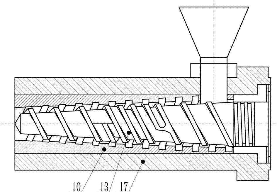
[0030] The third embodiment: the outer surface of the example screw and the inner surface of the barrel bushing are both cone-shaped, the diameter of the large end of the screw is D=90mm, the diameter of the small end is 60mm, the lead is 90mm, the number of thread starts is 2, and the long diameter The ratio is 20, right-handed, the solid conveying section has a screw groove depth of 6mm and a length of 5.8D; the melting section is a separate screw with a length of 8.2D and a secondary thread width of 5.0mm, and the solid phase screw groove depth is reduced from 6mm to 0mm , The depth of the liquid-phase screw groove gradually increases from 15.1mm to 23.5mm; the depth of the screw groove in the melt conveying section is 12mm, and the length is 6D. The diameter of the large end of the barrel bushing is 91mm, the diameter of the small end is 60.3mm, the number of grooves is 12, left-handed, the groove thread rise angle is 50°, and the groove depth of the initial end of the soli...
PUM
 Abstract
Description
Claims
Application Information
 - R&D
- Intellectual Property
- Life Sciences
- Materials
- Tech Scout
- Unparalleled Data Quality
- Higher Quality Content
- 60% Fewer Hallucinations
Browse by: Latest US Patents, China's latest patents, Technical Efficacy Thesaurus, Application Domain, Technology Topic, Popular Technical Reports.
© 2025 PatSnap. All rights reserved.Legal|Privacy policy|Modern Slavery Act Transparency Statement|Sitemap|About US| Contact US: help@patsnap.com


