Spinning apparatus of rotor spinning machine

A spinning machine and free-end technology, which is applied in the field of spinning mechanism of the free-end spinning machine, can solve the problems such as the temperature rise of the pulling nozzle.

Inactive Publication Date: 2014-05-07
RIETER CZ AS
View PDF10 Cites 1 Cited by
  • Summary
  • Abstract
  • Description
  • Claims
  • Application Information

AI Technical Summary

Problems solved by technology

Therefore, the heat loss generated in the stator of the electric rotary drive leads to a negative consequence of the temperature increase of the pulling nozzle

Method used


Image

  • Spinning apparatus of rotor spinning machine

Examples


Embodiment Construction

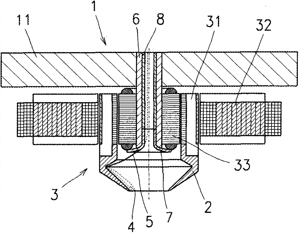
[0010] The open-end spinning machine comprises a plurality of spinning units 1 positioned adjacent to each other, each of them comprising a spinning rotor 2 coaxially mounted on radial and electromagnetic bearings and a drive system 3 on the electromagnetic function part 31 of the electric rotary drive. The radial electromagnetic bearing and the electromagnetic functional part 31 of the electric rotary drive of the drive system 3 are arranged between the stator 32 of the radial electromagnetic bearing and the stator 33 of the electric rotary drive, which is located in the spinning unit 1 In the cover 11, the cover 11 can be uncovered and installed on the main body of the spinning unit, in which the feeding device and picking device of the fiber sliver are arranged.

[0011] The spinning rotor 2 is formed by a body open on both sides, which is provided with an inlet hole for the entry of the picked fibers 4 and an outlet hole for the exit of the spun yarn 5, which continues to ...


PUM

PropertyMeasurementUnit
thermal conductivityaaaaaaaaaa

Abstract

A spinning apparatus of a rotor spinning machine. The apparatus has spinning shells (2) with openings at two sides are coaxially mounted on a radial electromangeitc bearing, an electromagnetic bearing and an electromagnetic functional unit (31) of an electrical rotation drive of a driving system (3), the spinning shell (2) is provided with an inlet opening for entry of dissolved fibers (4) and an outlet opening for discharging a spun yarn (5), the outlet opening extends to an aperture formed in a stator (33) of the electrical rotation drive, a discharge chute (7) of the yarn is connected to the aperture in the stator of the electrical rotation drive, and the stator of the electrical rotation drive is supported in a cover (11) of a spinning unit (1). A discharge chute is supported in a bushing (6) made of heat conducting material, and the bushing is supported in the stator of the electrical rotation drive and in the cover of the spinning unit and used for dissipating heat from the stator of the electrical rotation drive to the cover of the spinning unit.

Description

technical field [0001] The invention relates to an open-end spinning machine, the spinning rotor of which is coaxially installed on the radial electromagnetic bearing, the electromagnetic bearing and the electromagnetic functional part of the electric rotary driver of the drive system, and is formed by openings on both sides. The yarn rotor is provided with an inlet hole for the entrance of the picked fibers and an outlet hole for the exit of the spun yarn, which continues into a hole formed in the stator of the electric rotary drive, wherein the stator of the electric rotary drive The holes in the yarn are connected by the pulling nozzle of the yarn, and the stator of the electric rotary drive is installed in the cover of the spinning unit. Background technique [0002] An open-end spinning machine in which the spinning rotor is coaxially mounted on radial electromagnetic bearings and electromagnetic functional parts of the electromagnetic bearing and the electric rotary dr...

Claims


Application Information

Patent Timeline
Patent Type & Authority Applications(China)
IPC IPC(8): D01H4/08
CPCH02K1/187H02K9/22D01H4/14F16C32/048F16C2340/18H02K9/223
Inventor J·斯劳朋斯基J·斯托雷克P·塞姆拉德
Owner RIETER CZ AS
Why Eureka
Try Eureka