Fan failure braking device of aero-engine

A technology of braking device and fan, applied in gas turbine devices, machines/engines, jet propulsion devices, etc., can solve problems such as affecting the fuel economy of the engine and increasing the weight of the engine.

Active Publication Date: 2014-05-07
AECC COMML AIRCRAFT ENGINE CO LTD
View PDF6 Cites 13 Cited by
  • Summary
  • Abstract
  • Description
  • Claims
  • Application Information

AI Technical Summary

Problems solved by technology

[0003] The traditional method to deal with the FBO load is to use a larger design safety factor to strengthen the strength of the engine, such as strengthening the strength of the bearing support, strengthening the strength of the intermediate casing, streng...

Method used


Image

  • Fan failure braking device of aero-engine
  • Fan failure braking device of aero-engine
  • Fan failure braking device of aero-engine

Examples


Embodiment Construction

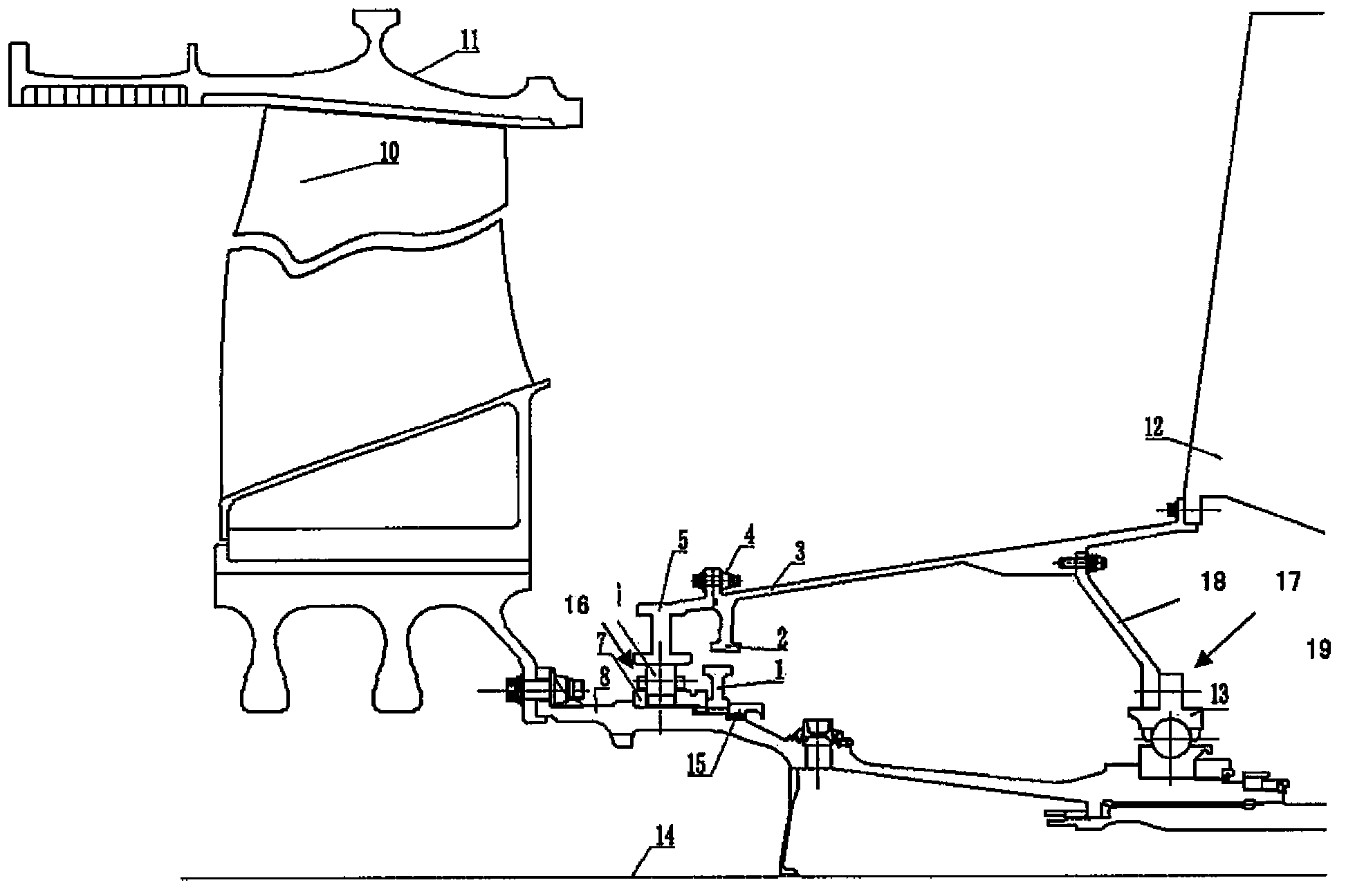
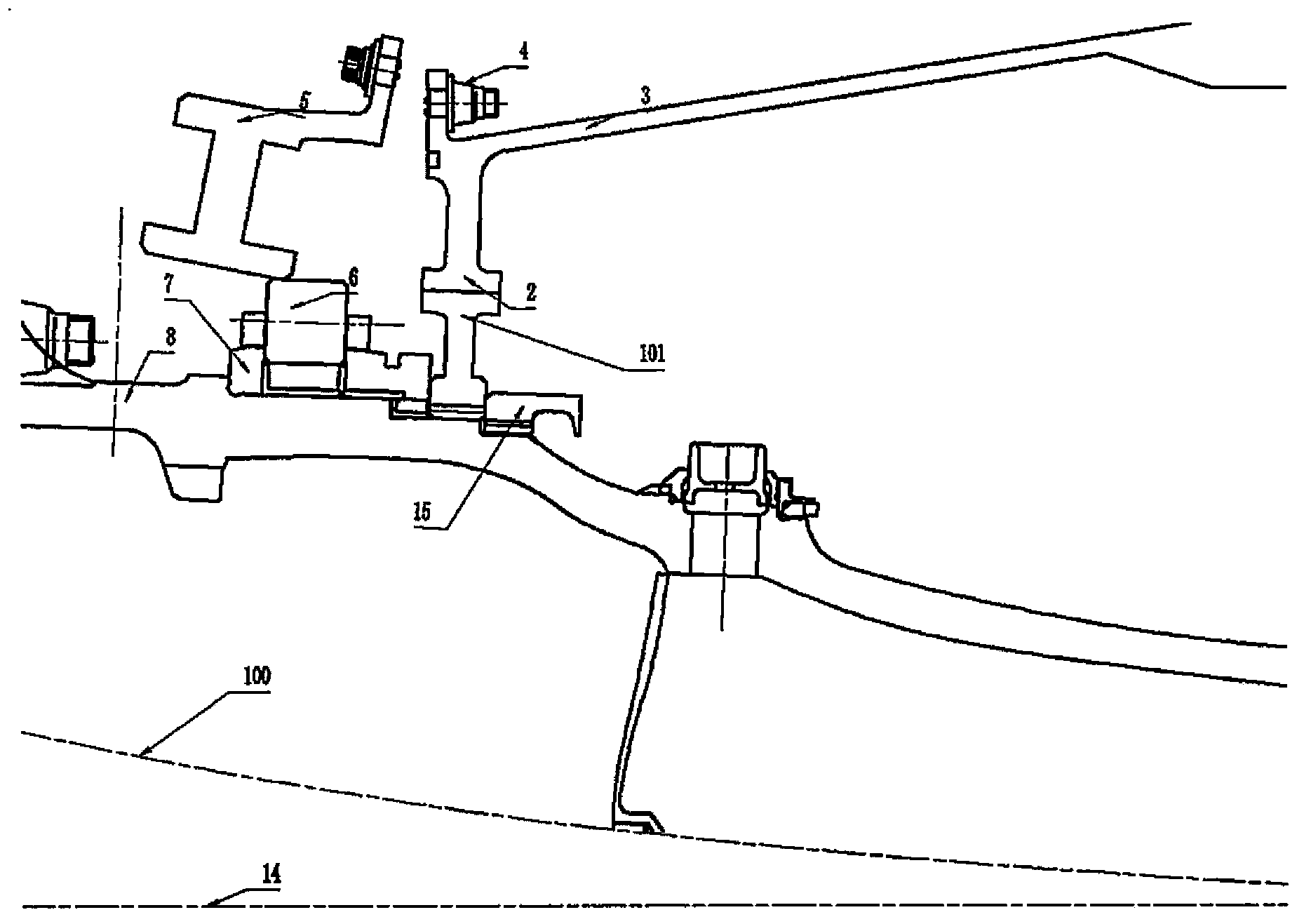
[0030] Such as figure 1 As shown, it shows a schematic structural diagram of the fan failure brake device when the engine is in normal operation. Specifically, the fan failure braking device mainly includes: a fan shaft 8 , a fan blade 10 , a bearing support 3 and a first bearing assembly 16 . Therein, the fan shaft 8 extends along the engine axis 14 , on which the rotor brake disc 1 is arranged. Mounted on the fan shaft 8 are fan blades 10 which are upstream relative to the rotor brake disc 1 in the direction of fluid flow. The fan blade 10 is mounted on the fan blade 10 and extends radially outward and is accommodated and protected by the fan case 11 . The rear end of the bearing support 3 is fixed to the intermediate casing 12, and the front end extends inwardly with a stator brake disc 2, which surrounds the rotor brake disc 1 circumferentially and is connected with the rotor brake disc 1 Radially spaced apart, the inner sides of the stator brake disc 2 are used as fric...


PUM


Abstract

A fan failure braking device of an aero-engine comprises a fan shaft, a fan blade, a bearing support piece and a bearing component, wherein a rotor brake disc is arranged on the fan shaft; the fan blade is mounted on the fan shaft; one end of the bearing support piece is mounted on an aero-engine casing, the bearing support piece is provided with a stator brake disc which circumferentially surrounds the rotor brake disc and is radially spaced from the rotor brake disc; one end of the bearing component is coupled with the other end of the fan shaft, and connected with the bearing support piece by a predetermined bending moment; when the fan blade fractures, the fan shaft deflects outwards, so that when the mutation bending moment between the bearing component and the bearing support piece exceeds the predetermined bending moment, the bearing component and the bearing support piece are disconnected, and thus the rotor brake disc and the stator brake disc are jointed. when the fan blade fails and fractures, rub-impact occurs between the rotor brake disc and the stator brake disc, limits the radial displacement of bending of the fan shaft and reduces the rotational speed of the fan shaft and the FBO (Fan Blade Out) load.

Description

technical field [0001] The invention relates to a fan failure braking device of an aero-engine. Background technique [0002] In the design of aero-engines, airworthiness inclusive regulations must be passed. The most stringent condition is that when the fan blades fall off, the engine can accommodate the damaged blades, and the engine must continue to operate at the windmill speed for more than 3 hours after the engine is turned off. When the fan blade falls off (FBO, Fan Blade Out), the engine runs at a relatively high speed, and the radial unbalanced load (FBO load) generated is very large, reaching tens of tons, and the radial unbalanced load is transmitted to the bearing support through the bearing The structure is then transferred to the intermediate casing, and then transferred to the aircraft through the installation joint system. If the engine is required to fully bear the FBO load, high requirements are placed on the structural strength of the engine. [0003] The...

Claims


Application Information

Patent Timeline
IPC IPC(8): F02C7/00
Inventor 娄俊岭孟祥海蔡真陈渊博孙煜
Owner AECC COMML AIRCRAFT ENGINE CO LTD
Why Eureka
Try Eureka