A power peak shaving heat and power cogeneration waste heat recovery device and its operating method

A technology of waste heat recovery device and combined heat and power generation, which is applied in the field of heat exchange device and power peak shaving cogeneration waste heat recovery device.

Active Publication Date: 2016-05-18
TSINGHUA UNIV
View PDF2 Cites 0 Cited by
  • Summary
  • Abstract
  • Description
  • Claims
  • Application Information

AI Technical Summary

Problems solved by technology

At the same time, the peak-to-valley difference of electric load is also expanding year by year, which makes it difficult for the power grid to regulate peak load.
[0003] At present, urban heating in northern my country still relies heavily on coal-fired boilers, resulting in high energy consumption and high pollution for heating.
Combined heat and power generation is an efficient heat supply method. However, my country's thermal power plants operate in the way of "heating power". In order to ensure heat supply, many thermal power plants have greatly limited their power output adjustment range. During the trough period, its power generation cannot be suppressed, thus seizing the space for wind power generation to be connected to the grid, so that wind farms have to limit their power generation output, resulting in a serious "wind abandonment" phenomenon in northern wind power-rich areas
[0004] The use of heat pump technology to recover the exhaust heat of cogeneration units can further improve the heating efficiency of cogeneration, but it cannot change its operation in the way of "heating power"; the combination of heat accumulator and cogeneration, the use of heat accumulator Suppressing fluctuations in heating output can enable cogeneration units to operate in the manner of "fixing heat with electricity", but when combined with the waste steam waste heat recovery technology of the power plant, it cannot guarantee the stable recovery of waste steam waste heat in the power plant

Method used


Image

  • A power peak shaving heat and power cogeneration waste heat recovery device and its operating method
  • A power peak shaving heat and power cogeneration waste heat recovery device and its operating method

Examples


Embodiment Construction

[0034] The present invention will be described in detail below in conjunction with the accompanying drawings and embodiments.

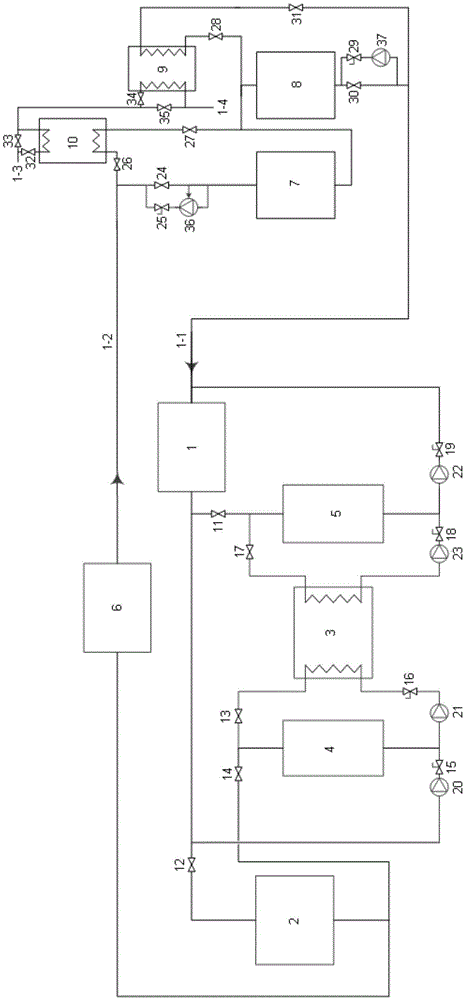
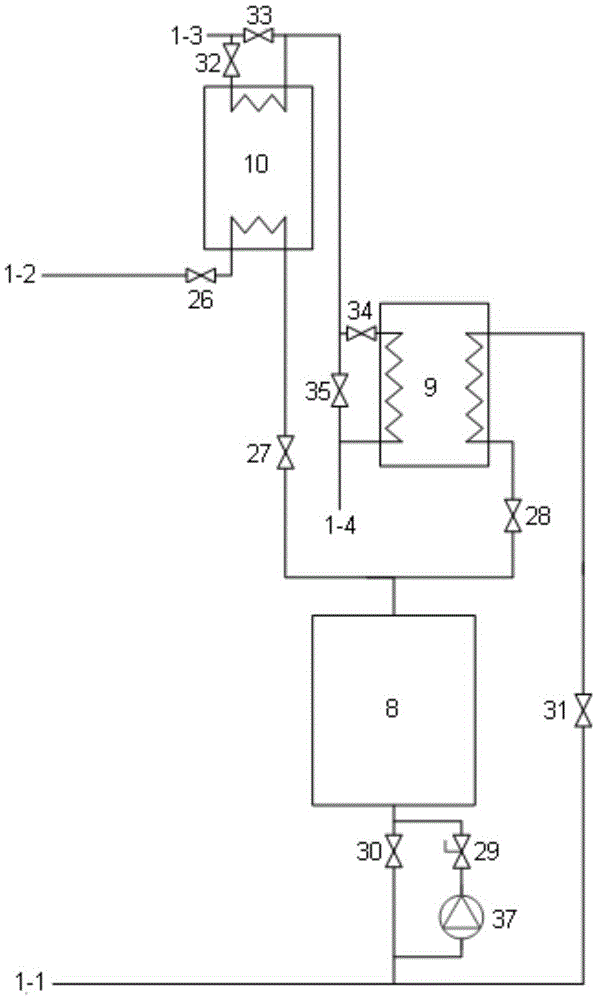
[0035] Such as figure 1 As shown, the device of the present invention is composed of the internal part of the power plant and the part of the heat exchange station.

[0036] The internal part of the power plant is mainly composed of condenser / water-water heat exchanger 1, waste heat recovery electric heat pump 2, energy storage electric heat pump 3, high temperature water storage tank 4, low temperature water storage tank 5, heating network heater 6, valve 11- 19 and circulating water pump 20-23 form. Among them, the inlet of the condenser / water-water heat exchanger 1 is connected to the return water pipeline 1-1 of the primary network, and the outlet of the condenser / water-water heat exchanger 1 is connected in parallel with valve 11, valve 12 and circulating water pump 20 respectively. import. The inlet of the waste heat recovery electric heat pu...


PUM


Abstract

The invention relates to an electric peaking combined heat and power (CHP) waste heat recovery device and an operating method thereof. The device comprises an inner power plant portion and a heat exchange station portion, wherein the inner power plant portion comprises a heat exchanger, a waste heat recovery electric heat pump, an energy-storing electric heat pump, high / low temperature water storing tanks, a heating network heater, a valve and a circulating water pump; the heat exchange station portion mainly comprises high / low temperature water storing tanks, an electric heat pump, a heat exchanger, a valve and a circulating water pump; as for the operating method of the device, the device can operate in periods of an electrical load trough, an electrical load flat peak and an electrical load peak respectively through combination of different valve switches, the high temperature water storing tank is used for balancing the difference between system heat supply amount and heating load, the low temperature water storing tank is used for stabilizing steam exhaust waste heat recovery amount, thereby, the problem that the electricity generation peaking capacity is limited due to mutual coupling of electricity generation and heat supply in traditional operating modes of 'heat determines electricity' is solved, a CHP unit can participate in power grid load regulation, the power grid regulating capacity can be improved so as to deal with the condition of constantly increasing of electrical load trough-to-peak difference, and the absorptive capacity of a power grid for wind power generation can be improved so as to reduce phenomena of 'fan suspending'.

Description

technical field [0001] The invention relates to a heat exchange device and its operation method, in particular to a power peak-shaving cogeneration waste heat recovery device and its operation method which utilize heat storage technology combined with heat and power cogeneration and power plant waste heat recovery, and belong to energy power technology field. Background technique [0002] The northern regions of my country belong to wind energy-rich regions. Wind power generation is developing rapidly in these regions. The installed capacity of wind power is increasing year by year, and the proportion of installed capacity of wind power to the total installed capacity is also increasing year by year. However, wind power generation has the characteristics of anti-load, that is, the output of wind power is larger during the low load of the power grid at night, and the output of wind power is smaller during the peak power consumption of the grid during the day. At the same tim...

Claims


Application Information

Patent Timeline
Patent Type & Authority Patents(China)
IPC IPC(8): F24D3/18F24D19/10
CPCY02B10/70Y02P80/15
Inventor 付林江亿吴彦廷孙健张世钢肖常磊杨巍巍唐道轲齐心
Owner TSINGHUA UNIV
Why Eureka
Try Eureka