Supercharge Your Innovation With Domain-Expert AI Agents!

Thermal image analysis device and thermal image analysis method

A technology of image analysis and analysis area, applied in the field of thermal image analysis devices, can solve the problems of cumbersome analysis mode, inconvenient use, difficult diagnosis and judgment, etc., to achieve the standardization and accuracy of reference images and analysis areas, and ensure correctness and convenience. , automatic or simple effects

Inactive Publication Date: 2014-05-07
MISSION INFRARED ELECTRO OPTICS TECH
View PDF4 Cites 0 Cited by
  • Summary
  • Abstract
  • Description
  • Claims
  • Application Information

AI Technical Summary

Problems solved by technology

Among them, the analysis area corresponds to a specific part that needs to be analyzed in the infrared thermal image, such as a point, line, surface and other area units or a combination of multiple area units; even if the analysis area is set in advance, it is still very inconvenient to use, because it is very inconvenient for the user As far as the Image 6 The analysis area F1 shown intuitively understands that the analysis area should be located in the thermal image of the subject. For example, when shooting the next subject of the same type, it is easy because the preset analysis area does not correspond to the thermal image of the subject. Correct location (such as the size of the thermal image of the subject, the position in the infrared thermal image, etc.), resulting in excessive dispersion of the analysis results, making it difficult to carry out effective diagnosis and judgment in the future
[0003] Secondly, the operation of analyzing locale settings is cumbersome and error-prone, such as Image 6 The number, type, position, size and other factors of the area units S01 and S02 in the analysis area F1 shown in the figure change, and the final analysis results may be different. surface, and then placed in the corresponding position of the thermal image of the subject) is quite cumbersome; the setting of the analysis area depends on the user's understanding of the analysis part of the subject. Different subjects have their own analysis parts, and the technical requirements high
Due to the above reasons, it is inconvenient to set complex analysis areas. At present, users use experience to perform simple analysis operations, such as setting the highest temperature to automatically capture. However, this extensive analysis method reduces the reference value of the analysis results during shooting.
[0004] Furthermore, setting the analysis mode corresponding to the analysis area is also a cumbersome operation. Different analysis mode settings will result in different analysis results; the analysis mode setting depends on the user's analysis position, analysis method, The understanding of diagnostic methods is required for setting, which requires extremely high technical requirements for users.

Method used


Image

  • Thermal image analysis device and thermal image analysis method
  • Thermal image analysis device and thermal image analysis method
  • Thermal image analysis device and thermal image analysis method

Examples


Embodiment approach

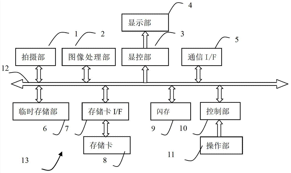
[0076] The image processing unit 2 is used to perform specified processing on the thermal image data obtained by the shooting unit 1. The processing of the image processing unit 2, such as correction, interpolation, false color, synthesis, compression, decompression, etc., is converted into a suitable display, Handling of data such as recording. The image processing unit 2 is used to perform prescribed processing on the thermal image data captured by the imaging unit 1 to obtain image data of infrared thermal images. For example, the image processing unit 2 performs non-uniformity correction on the thermal image data acquired by the imaging unit 1 , interpolation and other prescribed processing, perform pseudo-color processing on the thermal image data after the prescribed processing, and obtain image data of infrared thermal images; an implementation of pseudo-color processing, for example, according to the range or AD value of thermal image data (AD value) The setting range ...

Embodiment 1

[0232] In Embodiment 1, the analysis process is always carried out, and the analysis results are constantly updated, and the analysis results are displayed when the notification instruction from the user is received; but it can also be configured to perform the analysis only when the analysis key is pressed; or the analysis results The display can also be shown and refreshed all the time.

[0233] In addition, as shown in Figure 1703, the position parameters of the reference image can also be adjusted to match the thermal image IR1 of the subject in the infrared thermal image. Preferably, the reference image position setting part and the analysis area position setting part can The adjustment operation is performed to change at least one of the position, size, and rotation angle of the reference image and the analysis area in the infrared thermal image, and keep the prescribed positional relationship between the two unchanged. For example, when one of them is adjusted, the othe...

Embodiment 2

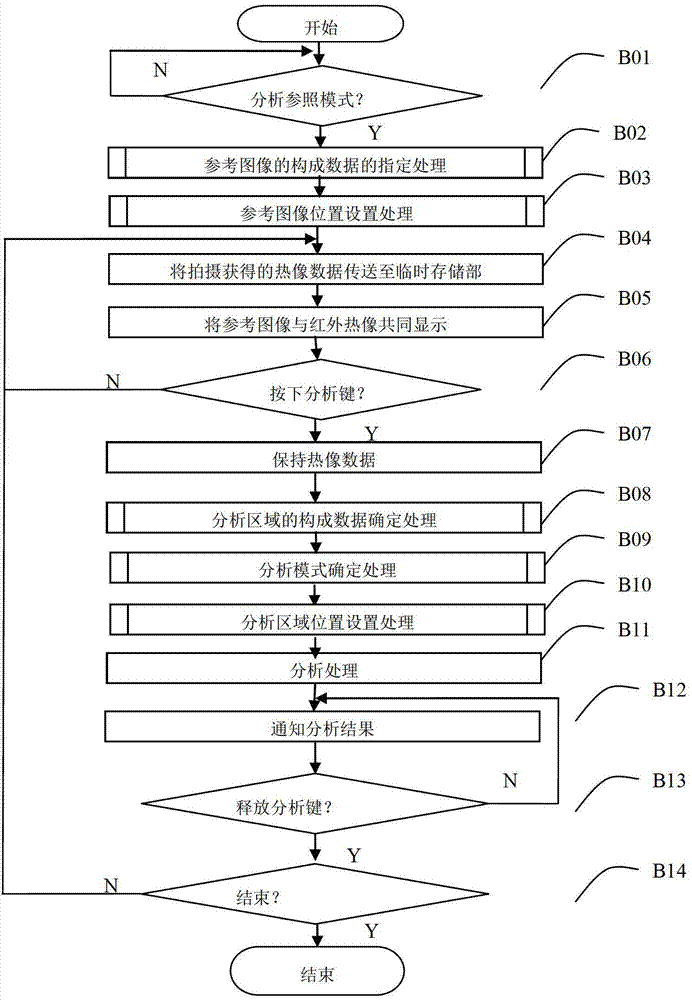
[0236] Embodiment 2 is a thermal imaging device 13 having the same structure as that shown in Embodiment 1. An analysis control program different from that of Embodiment 1 is stored in the flash memory 9. In response to an analysis instruction from a user, the thermal image data will be frozen, displayed and maintained. , and perform analysis to obtain the analysis result; and, store in the flash memory 9 such as Figure 4 memory contents as shown, and as Figure 13 configuration shown.

[0237] refer to Figure 23 To illustrate the control flow.

[0238] In step B01, the control unit 10 continuously monitors whether the analysis and reference mode is selected, and if so, proceeds to step B02.

[0239] In step B02, the control unit 10 performs a process of specifying the constituent data of the reference image. see details Figure 18 Steps S101-S107 in.

[0240] In step B03, the control unit 10 performs setting processing of the position parameters of the reference image...


PUM


Abstract

The invention discloses a thermal image analysis device and a thermal image analysis method, and relates to the application field of thermal imaging devices and infrared thermal image detection. A thermal imaging device in the prior excessively depends on subjective experiences of a user during photographing to set an analysis area for a thermal image of a photographed subject, thereby being complicated in operation and causing the discreteness of an analysis result to be too high. The thermal image analysis device the thermal image analysis method display a superimposed reference image embodying preset morphological characteristics of the photographed subject in infrared thermal imaging, the reference image is used as a visual reference for photographing the thermal image of the photographed subject, thereby enabling the set analysis area to be convenient for photographing the next subject of the same type, and reducing setting operations of the user. Furthermore, the thermal image of the photographed subject can be analyzed according to an analysis area corresponding to the reference image and the specified analysis mode to obtain an analysis result. Therefore, a common user can also achieve a good photography skill level.

Description

technical field [0001] The thermal image analysis device and thermal image analysis method of the present invention relate to thermal image devices, thermal image processing devices, and the application fields of infrared detection. Background technique [0002] At present, users need to rely on subjective experience to manually set an analysis area for a specific part of the subject's thermal image for analysis to obtain thermal image analysis results. Among them, the analysis area corresponds to a specific part that needs to be analyzed in the infrared thermal image, such as a point, line, surface and other area units or a combination of multiple area units; even if the analysis area is set in advance, it is still very inconvenient to use, because it is very inconvenient for the user As far as the Figure 6 The analysis area F1 shown intuitively understands that the analysis area should be located in the thermal image of the subject. For example, when shooting the next sub...

Claims


Application Information

Patent Timeline
Patent Type & Authority Applications(China)
IPC IPC(8): G01J5/10H04N5/33
CPCG01J2005/0077H04N5/33G06T7/74G06T1/0007G06T2207/10004G06T2207/10048G06T2207/20104H04N23/23G06T2207/20036G06T2207/20116G06T2207/30012G06T2207/30196
Inventor 王浩
Owner MISSION INFRARED ELECTRO OPTICS TECH
Features
  • R&D
  • Intellectual Property
  • Life Sciences
  • Materials
  • Tech Scout
  • Unparalleled Data Quality
  • Higher Quality Content
  • 60% Fewer Hallucinations
Learn More