Compensation method of steel ball surface detect measuring system based on optical fiber sensing

A fiber optic sensing and measurement system technology, applied in measuring devices, material analysis through optical means, instruments, etc., can solve problems such as changes in the received light intensity of sensors

Inactive Publication Date: 2014-05-07
UNIV OF JINAN
View PDF9 Cites 4 Cited by
  • Summary
  • Abstract
  • Description
  • Claims
  • Application Information

AI Technical Summary

Problems solved by technology

However, the change of light intensity is often not only affected by the gap, many factors will cause the change of the light intens

Method used


Image

  • Compensation method of steel ball surface detect measuring system based on optical fiber sensing
  • Compensation method of steel ball surface detect measuring system based on optical fiber sensing
  • Compensation method of steel ball surface detect measuring system based on optical fiber sensing

Examples


Embodiment Construction

[0036] A compensation method for optical fiber sensors in the measurement of surface defects of steel balls, comprising the following steps:

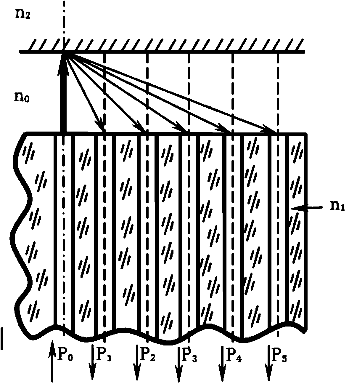
[0037] Step 1. For the sensor structure in which a single optical fiber emits and multiple groups of optical fibers receive scattered light, the incident optical power P is obtained by measuring with an optical power meter 0 And the corresponding optical power P received by multiple groups of fibers 1 ,P 2 ,...,P n ;

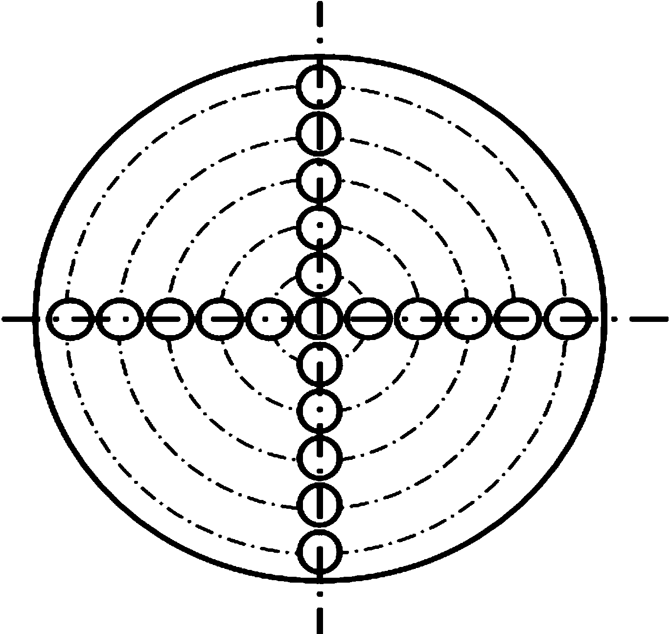
[0038] Step 2 versus the P obtained in step 1 1 ,P 2 ,...,P n Use multi-channel high-speed synchronous data acquisition boards for data acquisition to obtain digital signals of n-channel light intensity, according to figure 2 It can be seen from the structure of the optical fiber sensor that the reflected light intensity received by different groups of receiving optical fibers comes from different spherical micro-element surfaces. Since the surface of the steel ball is a curved surface, the inclination angles of di...


PUM


Abstract

The invention particularly discloses a compensation method of a steel ball surface detect measuring system based on optical fiber sensing. The compensation method of the steel ball surface detect measuring system based on optical fiber sensing comprises the following steps: step 1, for a sensor structure that a single optical fiber transmits scattered light and a plurality of groups of optical fibers receive scattered light, measuring by an optical power meter so as to obtain detection incidence power P0 and corresponding light power P1, P2,..., and Pn received by multiple groups of optical fibers; step 2, collecting data of the light power P1, P2,..., and Pn which are obtained in the step 1 by a multi-path high-speed synchronous data collecting plate, thereby obtaining digital signals with N light intensity; summing the N groups of light intensity so as to obtain P=P1+P2+P3+...+Pn; step 3, carrying out division operation on the P, P1, P2, ..., and PN which are obtained from the step 2, that is, dividing multiple groups of received light intensity by each group of received light intensity so as to obtain specific values P/P1, P/P2, ..., and P/P(n-1), thereby obtaining the light intensity specific values when the sensor and a measured surface are oblique at different angles; step 4, establishing a function of a clearance varying along with the specific value; step 5, determining the coefficients a0, a1, a2, ..., and a(n-1); and step 6, substituting the coefficient values from the step 5 into the formula (1), thereby obtaining the accurate gap value.

Description

technical field [0001] The invention relates to a compensation method for an intensity modulation optical fiber displacement sensor in the detection of steel ball surface defects. Background technique [0002] The present invention proposes based on the fact that bearings are important basic components in the machinery industry, and steel balls are the rolling elements of ball bearings. Their quality plays a decisive role in the motion accuracy, life, and performance of the bearings. The impact on the quality of the steel ball is particularly obvious. After processing, some steel balls will have pitting, spots, burns, scratches, scratches, pits and other defects on the surface. These surface defects will cause the ball bearing to generate large noise during rotation. And vibration are the key factors restricting the improvement of ball bearing quality. [0003] In the patent application number (201320066563.1), a fiber optic sensor system for detecting surface defects of st...

Claims


Application Information

Patent Timeline
IPC IPC(8): G01N21/952
Inventor 马玉真王新华孙选张辉李国平
Owner UNIV OF JINAN
Why Eureka
Try Eureka