Method for quickly searching grounding fault point of electrical equipment
A technology for ground faults and electrical equipment, which is applied in the direction of measuring electricity, measuring electrical variables, measuring devices, etc., and can solve the problems of lower quality of important load products, large equipment damage, and inability to accurately locate ground fault points.
- Summary
- Abstract
- Description
- Claims
- Application Information
AI Technical Summary
Problems solved by technology
Method used
Image
Examples
Embodiment 1
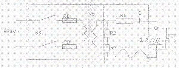
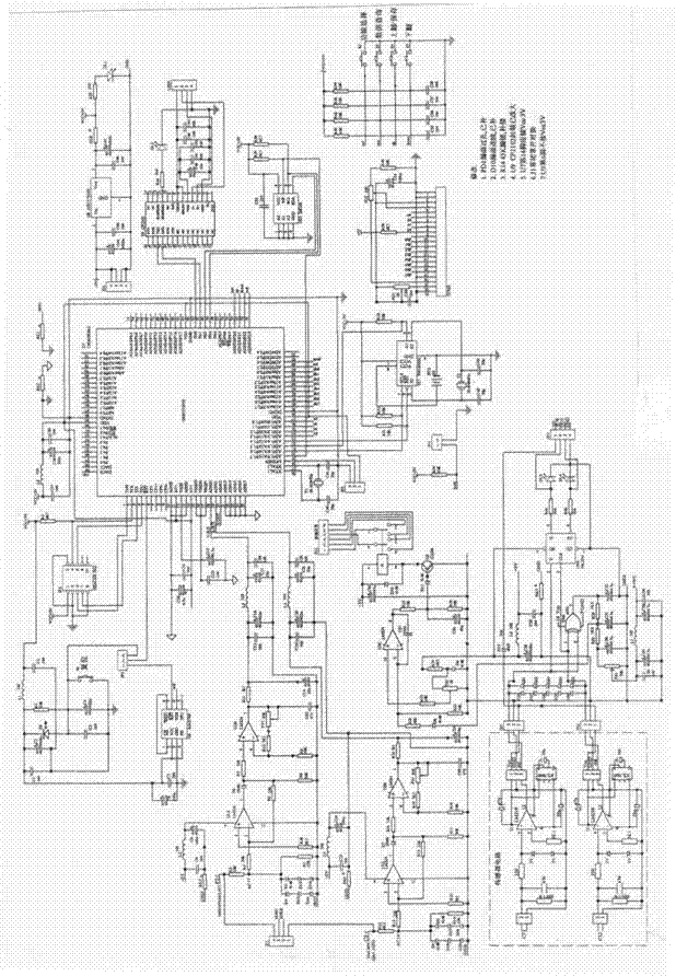
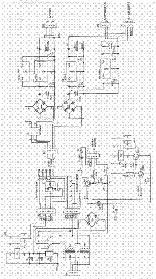
[0014] Example 1: A quick tester for electrical circuit grounding faults, which consists of three parts: a converter, a signal operation box and a phase angle meter. Various components of the main circuit are installed in the converter; there are 3 integrated circuit boards in the signal operation box and 1 operation panel; the phase angle meter is a flexible current converter; the main circuit of the converter is connected to the circuit of the signal operation box and the phase angle meter respectively, and is controlled by the power switch, start button and adjustment knob on the operation panel of the signal operation box Carry out operation and control, use the special equipment to detect the change of the position of the current transformer, and find the fault point. The technical parameters of the tester are:
[0015] 1. Power supply: AC 380V(A-B) 50-60Hz
[0016] 2. Output voltage: AC 0-50 (continuously adjustable)
[0017] 3. Output current: 2A
[0018] 4...
Embodiment 2
[0023] Example 2: The specific method of accurately judging the fault point is to use a special flexible opening. The current transformer sends any point current on the L side or C side to the phase comparator for comparison. Finally, the dichotomy or golden section method can be used to quickly Find the point of failure.
Embodiment 3
[0024] Example 3: Specific operation method:
[0025] Select a notebook computer and install the driver and application program: Connect the instrument to the computer with a USB cable, prompting that new hardware has been found; put the accompanying CD into the CD-ROM drive, install the RS232-USB driver and the instrument driver; put the power switch on In the closed position, the output voltage adjustment knob is placed at zero position; adjust the initial state of the instrument; connect the power, turn on the power switch, the LCD screen lights up and displays the initialization interface, and the zero indicator light is on; if the zero indicator light is off, it is The output voltage adjustment knob is not at the zero position, the protection circuit is interlocked, and the instrument cannot be started. Please put the output voltage adjustment knob at the zero position, and the zero position indicator light is on; press the start button, the start indicator light is on, ...
PUM
 Abstract
Description
Claims
Application Information
 - R&D
- Intellectual Property
- Life Sciences
- Materials
- Tech Scout
- Unparalleled Data Quality
- Higher Quality Content
- 60% Fewer Hallucinations
Browse by: Latest US Patents, China's latest patents, Technical Efficacy Thesaurus, Application Domain, Technology Topic, Popular Technical Reports.
© 2025 PatSnap. All rights reserved.Legal|Privacy policy|Modern Slavery Act Transparency Statement|Sitemap|About US| Contact US: help@patsnap.com


