Supercharge Your Innovation With Domain-Expert AI Agents!

A kind of vehicle compensation capacitance detection method and system

A technology for compensating capacitors and trains, which is applied in the field of detection methods and systems for vehicle-mounted compensation capacitors. It can solve problems such as poor contact, affecting quality, and time-consuming and labor-intensive problems, and achieves the effects of easy maintenance and upgrading, saving space, and improving detection efficiency.

Active Publication Date: 2016-07-06
CHINA ACADEMY OF RAILWAY SCI CORP LTD +2
View PDF9 Cites 1 Cited by
  • Summary
  • Abstract
  • Description
  • Claims
  • Application Information

AI Technical Summary

Problems solved by technology

However, due to environmental, weather and human factors, the compensation capacitor will have electrical characteristic parameters drift or poor contact, etc., resulting in aging, failure or loss of the compensation capacitor, which will directly affect the quality of track circuit signal transmission, transmission distance and The normal operation of the train control system, so it is necessary to check the compensation capacitor frequently
[0003] In order to meet the needs of the railway electrician for the detection of compensation capacitors, relevant railway departments or research institutions have developed some special track circuit parameter comprehensive testers, but the testers need to judge their working status through direct measurement, so practical applications need Manual detection of each capacitor is time-consuming, labor-intensive, inefficient and dangerous

Method used


Image

  • A kind of vehicle compensation capacitance detection method and system
  • A kind of vehicle compensation capacitance detection method and system
  • A kind of vehicle compensation capacitance detection method and system

Examples


Embodiment 1

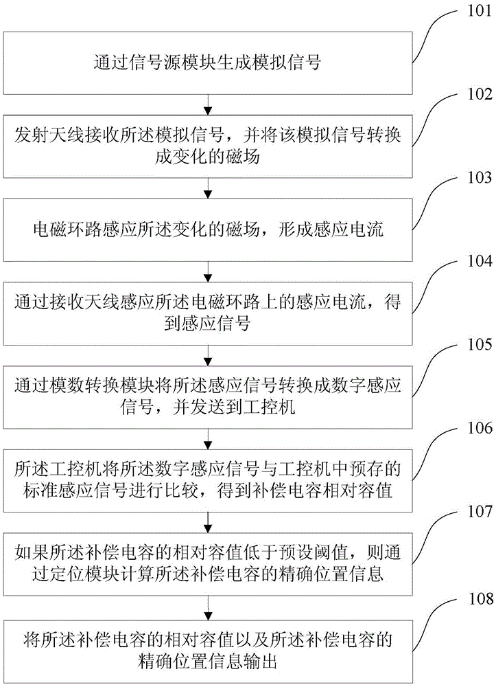
[0052] Such as figure 1 As shown, it is a flow chart of a vehicle-mounted compensation capacitance detection method in this embodiment, which specifically includes the following steps:

[0053] Step 101, generate an analog signal through a signal source module.

[0054] Step 102, the transmitting antenna receives the analog signal, and converts the analog signal into a changing magnetic field.

[0055] Step 103, the electromagnetic loop induces the changing magnetic field to form an induced current;

[0056] The electromagnetic loop is composed of two adjacent wheelsets of the train and the rails on both sides of the train. The electromagnetic loop also includes a compensation capacitor, which is located between the two wheelsets and is connected to the two wheelsets. Two wheelsets are connected in parallel on the rails on both sides of the train.

[0057] In step 104, the receiving antenna senses the induced current on the electromagnetic loop to obtain an induced signal. ...

Embodiment 2

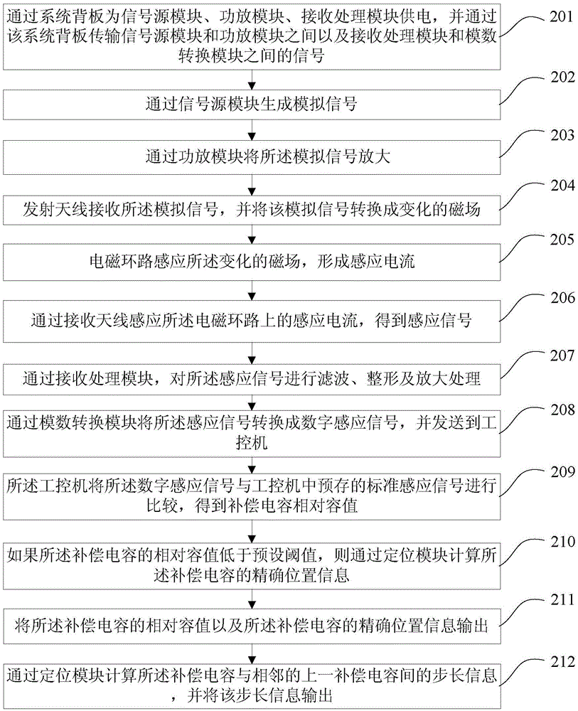
[0063] Such as figure 2 As shown, it is a flow chart of a vehicle-mounted compensation capacitance detection method in this embodiment, including the following steps:

[0064] Step 201, supply power to the signal source module, the power amplifier module, and the receiving processing module through the system backplane, and transmit signals between the signal source module and the power amplifier module and between the receiving processing module and the analog-to-digital conversion module through the system backplane.

[0065] This step is performed in parallel with all the following steps, providing service and support for each of the following steps.

[0066] Step 202, generate an analog signal through the signal source module.

[0067] The frequency of the analog signal can be adjusted by the signal source module.

[0068] Step 203, amplify the analog signal through a power amplifier module.

[0069] Wherein, the amplification factor can be adjusted by the power amplifie...

Embodiment 3

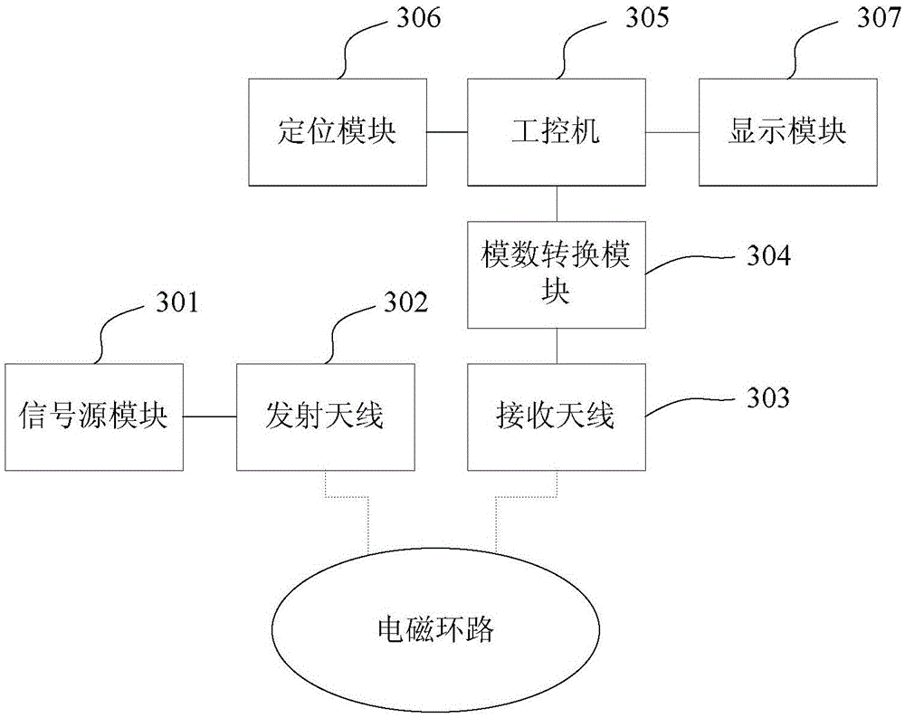
[0092] Such as image 3 As shown, it is a structural diagram of a vehicle-mounted compensation capacitance detection system in this embodiment, including the following modules:

[0093] A signal source module 301, configured to generate an analog signal and adjust the frequency of the analog signal;

[0094] The transmitting antenna 302 is used to receive the analog signal and convert the analog signal into a changing magnetic field so that the electromagnetic loop forms an induced current; Composed of steel rails, the electromagnetic loop also includes a compensation capacitor, which is located between the two wheel pairs and connected in parallel with the two wheel pairs on the rails on both sides of the train;

[0095] The receiving antenna 303 is used to sense the induced current on the electromagnetic loop to obtain the induced signal;

[0096] An analog-to-digital conversion module 304, configured to convert the sensing signal into a digital sensing signal and send it ...


PUM


Abstract

The invention relates to the field of track circuit compensation capacitor detection in the railway industry, and particularly provides a method and system for detecting a vehicle-mounted compensation capacitor. The method comprises the steps that an analog signal is generated and sent to an electromagnetic loop to form a native electromagnetic field; the electromagnetic loop is composed of two adjacent wheel sets of a train and steel rails on the two sides of the train and further comprises the compensation capacitor located between the two wheel sets, and the compensation capacitor and the two wheel sets are connected to the steel rails on the two sides of the train in parallel; a receiving antenna inducts a secondary electromagnetic field on the electromagnetic loop, and therefore an induction signal of an induction current is obtained; the induction signal is compared with a standard induction signal prestored in an industrial control computer to obtain the state information of the compensation capacitor; the precise position information of the compensation capacitor is calculated through a positioning module, the relative capacitance value of the compensation capacitor and the precise position of the fault compensation capacitor can be conveniently and rapidly judged.

Description

technical field [0001] The invention relates to the detection of compensation capacitors for track circuits in the railway industry, in particular to a method and system for detecting compensation capacitors on vehicles. Background technique [0002] In recent years, in order to meet the needs of high-speed railway transportation, electrically insulated track circuits have been widely used across the country. In order to prolong the transmission distance of the signal as much as possible, several compensation capacitors are installed at equal intervals on the electrically insulated track circuit. However, due to environmental, weather and human factors, the compensation capacitor will have electrical characteristic parameters drift or poor contact, etc., resulting in aging, failure or loss of the compensation capacitor, which will directly affect the quality of track circuit signal transmission, transmission distance and For the normal operation of the train control system,...

Claims


Application Information

Patent Timeline
Patent Type & Authority Patents(China)
IPC IPC(8): G01R31/08G01R27/26
Inventor 吴楠王卫东高利民谢保锋孟景辉刘玉江
Owner CHINA ACADEMY OF RAILWAY SCI CORP LTD
Features
  • R&D
  • Intellectual Property
  • Life Sciences
  • Materials
  • Tech Scout
  • Unparalleled Data Quality
  • Higher Quality Content
  • 60% Fewer Hallucinations
Learn More