A long-lived fiber for high-stress environments
A long-life, high-stress technology, applied in the direction of multi-layer core/cladding optical fiber, cladding optical fiber, etc., can solve problems that affect customer perception, reduce service life, and trouble the development of optical fiber cold splicing technology, so as to improve dynamic Fatigue parameters, long service life, effect of improving resistance to external impurities
- Summary
- Abstract
- Description
- Claims
- Application Information
AI Technical Summary
Problems solved by technology
Method used
Image
Examples
Embodiment 1
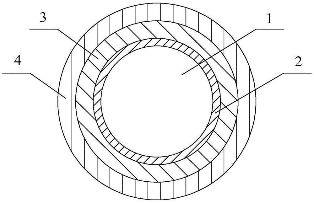
[0024] The first coating 2 outside the silica optical fiber 1 is titanium dioxide with a thickness of 3nm; the thickness of the second coating 3 and the third coating 4 are both 30 μm; Polypropylene resin, the third coating 4 is a polypropylene resin with a Young's modulus of 1200MPa.
[0025] During preparation, firstly, a quartz rod is fused and drawn into a quartz optical fiber 1 by using a high-temperature furnace, and a 3nm-thick titanium dioxide layer is deposited on its surface through a plasma chemical vapor deposition device arranged next to the lower furnace mouth of the high-temperature furnace, that is, the first coating 2. Then prepare the second coating 3 and the third coating 4 by dry + wet method, and use the sealing pressure coating method to first coat the polypropylene resin (softer polyacrylic resin) with a Young's modulus of 0.5Mpa in a thickness of 30 μm, Use ultraviolet light to cure it from liquid to solid; then use sealing pressure to coat and coat po...
Embodiment 2
[0030] The first coating 2 outside the silica optical fiber 1 is carbon, and its thickness is 3 nm; the thickness of the second coating 3 and the third coating 4 are both 30 μm; Polypropylene resin, the third coating 4 is a polypropylene resin with a Young's modulus of 700MPa.
[0031] The method of preparation is the same as that of Example 1, and will not be repeated here, except that the second coating is coated with a polypropylene resin with a Young's modulus of 0.3 MPa using the sealing pressure coating method; the third coating 4 is a polypropylene resin with a Young's modulus of 700 MPa.
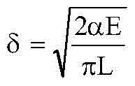
[0032] In this embodiment, since the service life prediction model of the optical fiber usually adopts the following life calculation formula:
[0033] t s = t p ( σ p σ s ) ...
Embodiment 3
[0036] The first coating 2 outside the silica optical fiber 1 is a high-density polyethylene compound with a thickness of 0.5 μm, the thickness of the second coating 3 and the third coating 4 are both 30 μm; the second coating 3 is Young’s A polypropylene resin with a modulus of 0.7MPa, and the third coating 4 is a polypropylene resin with a Young's modulus of 800MPa.
[0037] During the preparation, firstly, the quartz rod is fused and drawn into the quartz optical fiber 1 by using a high-temperature furnace, and then a high-density polyethylene compound is coated through a mold to form a first coating 2, which is cured by ultraviolet light. Then adopt the wet + wet method, the second coating 3 and the third coating 4 are coated together by the sealing pressure coating method, wherein the second coating 3 is in the third coating 4, and then the two layers are coated with ultraviolet light Together the coatings cure from liquid to solid.
[0038] In this embodiment, since the...
PUM
| Property | Measurement | Unit |
|---|---|---|
| thickness | aaaaa | aaaaa |
| thickness | aaaaa | aaaaa |
| thickness | aaaaa | aaaaa |
Abstract
Description
Claims
Application Information
 - R&D
- Intellectual Property
- Life Sciences
- Materials
- Tech Scout
- Unparalleled Data Quality
- Higher Quality Content
- 60% Fewer Hallucinations
Browse by: Latest US Patents, China's latest patents, Technical Efficacy Thesaurus, Application Domain, Technology Topic, Popular Technical Reports.
© 2025 PatSnap. All rights reserved.Legal|Privacy policy|Modern Slavery Act Transparency Statement|Sitemap|About US| Contact US: help@patsnap.com


