Power tunnel cable monitoring method with self-test and hot-swapping functions

A power tunnel, hot-swap technology, applied in electrical program control, comprehensive factory control, measurement devices, etc., can solve the problems of difficult fault location, hidden dangers of uncertain maintenance work, and high maintenance costs, to simplify maintenance work and shorten the time. Maintenance time and effect of ensuring safety

Active Publication Date: 2016-08-31
李成
View PDF6 Cites 0 Cited by
  • Summary
  • Abstract
  • Description
  • Claims
  • Application Information

AI Technical Summary

Problems solved by technology

[0004] 1. The method of power tunnel status monitoring system is to adopt the method of multi-in-one design of various functional systems. The advantage of this system architecture is that the system design and implementation are relatively easy, and the manufacturing cost of the equipment is saved, but the disadvantages of this method are also obvious. For example, it is difficult to locate the fault. Once the system fails, the whole system will be paralyzed, and the operation of the subsystems will affect each other. The maintenance technical requirements are relatively professional. If you are not familiar with the entire system, you will have no way to maintain it. The maintenance time is longer and the maintenance cost is higher.
[0005] 2. Since it is impossible to solve the problem of signal coverage of wireless devices under the tunnel and the problem of power supply of the device itself for a long time (over 1.5 years), it can only be networked in wired mode, and it cannot take into account the situation of trenches, shallow trenches, and remote tunnels
[0006] 3. It can’t solve the power supply and communication problems of long-distance equipment well, so the system networking is basically adopted to build a new power supply network and transmission network. In this way, in the harsh environment of the tunnel, two sets of failure points will undoubtedly be added to provide follow-up Maintenance work brings many uncertain hidden dangers

Method used


Image

  • Power tunnel cable monitoring method with self-test and hot-swapping functions

Examples


Embodiment Construction

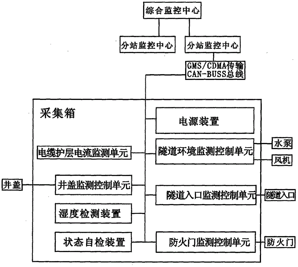
[0034] The present invention forms a network according to the above method: the state monitoring and equipment control unit, the data transmission unit, and the data monitoring center are connected in series.

[0035] The cable grounding wire monitoring is mainly used for monitoring the grounding circulation of the metal sheath of the power system 110KV and above. The design of the cable system is based on the tunnel laying method used for cable laying.

[0036] The communication between each detection device and the system and the power supply of each detection device of the present invention share a pair of armored power twisted pair communication cables with a thickness of 0.5 square millimeters. It is not necessary to establish optical network communication, and the communication distance is greater than 5 kilometers. Twisted-pair communication cables can connect up to 127 devices with bus technology, no optical network failure and low-voltage current interface failure, and...


PUM


Abstract

The invention discloses an electric power tunnel cable monitoring system with self-check and hot swap functions. The system comprises a cable sheath current monitoring unit, a tunnel environment monitoring control unit, a well cover monitoring control unit, a tunnel inlet monitoring control unit and a fire door monitoring control unit. The state monitoring and equipment control units are independently installed on a mainboard in an acquisition box respectively in an insertion mode, and hot swap is supported; and data transmission is GMS / CDMA transmission or CAN-BUSS bus transmission. At the same time, the mainboard is also provided with a humidity detection device for detecting the environment inside the acquisition box at any time and sending correlation detection data to a substation monitoring center. The system is provided with a state self-check device for performing self-check on the working state of each unit at any time so that once a fault occurs in the system or in an individual unit or in an individual detector, working personnel can clearly and rapidly position a fault position.

Description

technical field [0001] The invention relates to an underground tunnel monitoring system of a power supply system, which is used for monitoring the running state of a power supply network in an urban underground tunnel. Background technique [0002] With the advancement of smart grid construction and the rapid development of urban power grid work, the safety of the power grid inside the tunnel has been paid more and more attention by the line maintenance department. It is necessary to ensure the normal operation of trench or shallow trench power cables from multiple links, such as: power tunnels Manhole cover anti-theft and illegal opening monitoring, power tunnel comprehensive environment monitoring, power cable grounding current monitoring, power tunnel entrance access control and fire door monitoring, etc. [0003] In order to meet the above needs, some power tunnel status monitoring systems have been produced, but after analysis and testing by the applicant, some shortcom...

Claims


Application Information

Patent Timeline
Patent Type & Authority Patents(China)
IPC IPC(8): G05B19/418G01D21/02
Inventor 李成
Owner 李成
Why Eureka
Try Eureka