Dual-redundancy telescope tracking device for astronomical telescope

An astronomical telescope and tracking device technology, applied in the field of tracking racks, can solve the problems of complex structure mode mechanism, difficult to meet design requirements, long development process, etc., and achieve a wide speed regulation range, low power consumption and low maintenance cost. Effect

Inactive Publication Date: 2014-05-07
NANJING INST OF ASTRONOMICAL OPTICS & TECH NAT ASTRONOMICAL OBSE
View PDF4 Cites 17 Cited by
  • Summary
  • Abstract
  • Description
  • Claims
  • Application Information

AI Technical Summary

Problems solved by technology

Gear transmission is generally used in medium and small astronomical telescopes, and friction drive is mostly used in large and medium-sized astronomical telescopes. When gear transmission is used in large and super large astronomical telescopes, there are the following difficulties: processing of large and extra large precision gears and worm gears There is very little equipment, and the processing equipment specially developed for ultra-large precision gears and worm gears is difficult to meet the actual design requirements due to its complex technology, high cost, and long development process. In addition, there are gear transmission gaps in the drive system, and the rigidity of the system is weak. Factors such as complex structural model and mechanism; friction drive will cause crawling problems when running at ultra-low speed in ultra-large-caliber astronomical telescopes

Method used


Image

  • Dual-redundancy telescope tracking device for astronomical telescope
  • Dual-redundancy telescope tracking device for astronomical telescope
  • Dual-redundancy telescope tracking device for astronomical telescope

Examples


Embodiment 1

[0027] Embodiment 1 is used for a telescope-driven comprehensive experimental platform. Main technical indicators: Wide range of speed regulation: 0.05″ / s at low speed, 20° / s at high speed, no crawling phenomenon at low speed operation. The overall instrument has high reliability and low failure rate; the system can The target is continuously tracked, and the rotation range is adjustable within the range of plus or minus 0~360° or even larger.

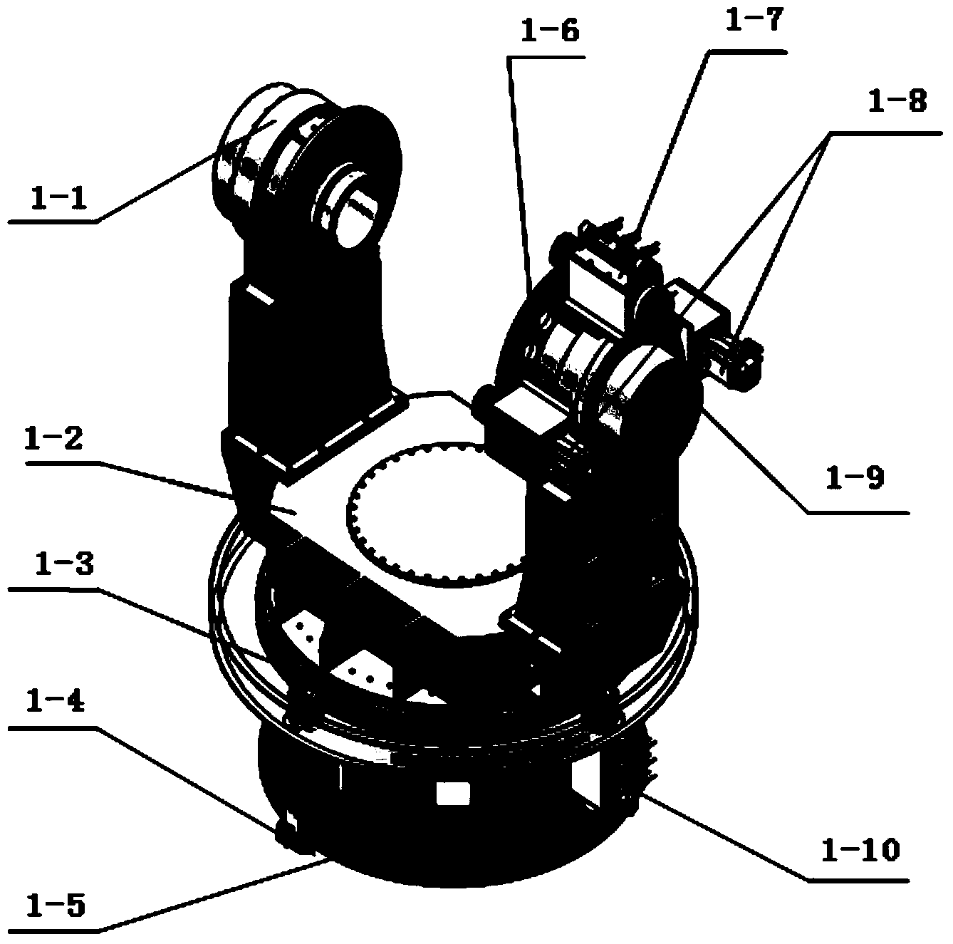
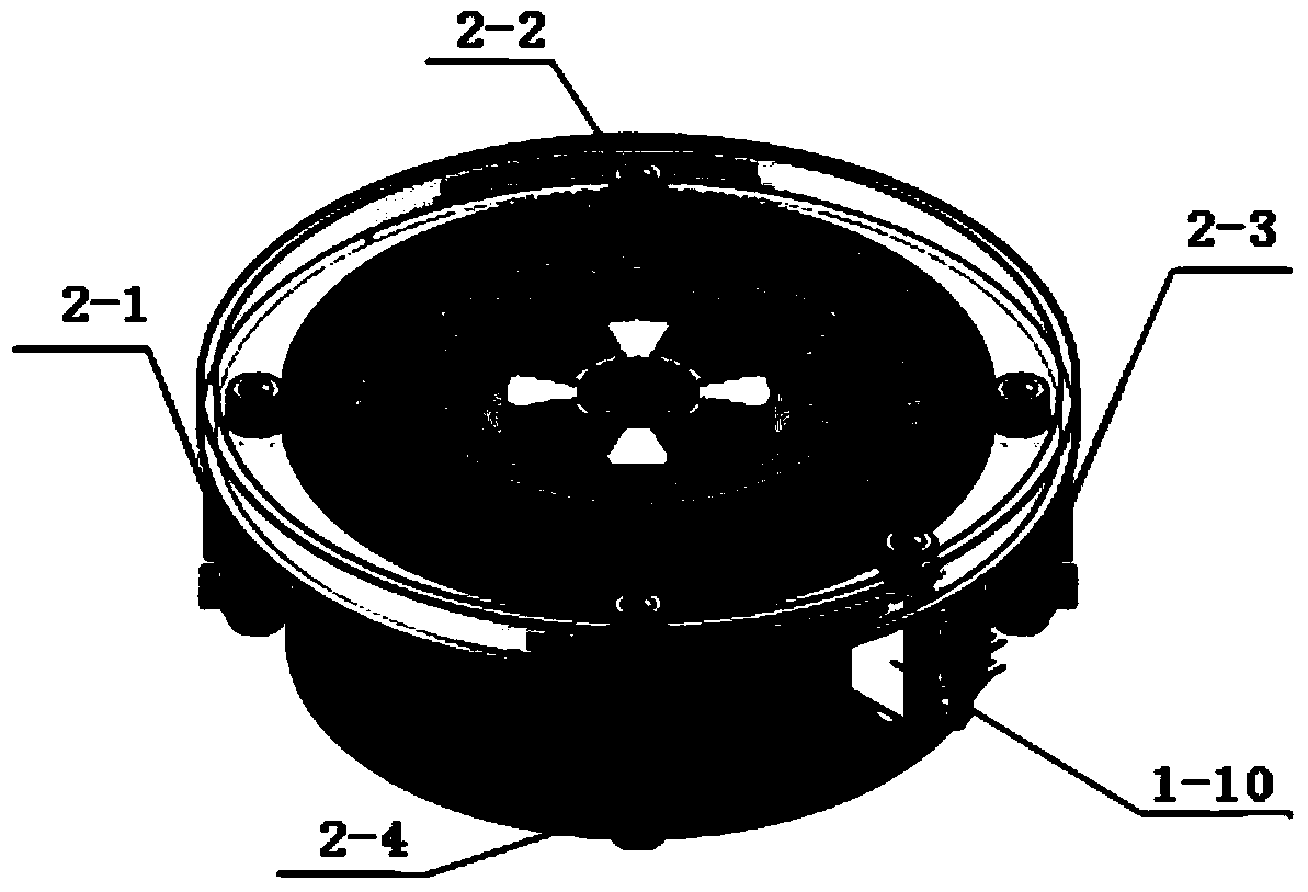
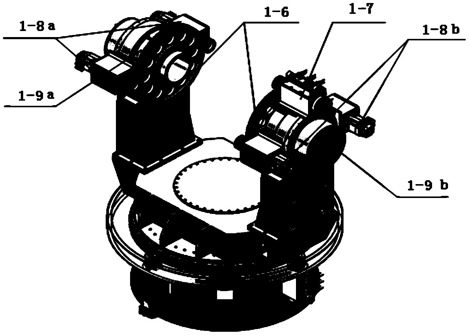
[0028] The dual-redundant tracking frame of the telescope is mainly composed of dual-redundant azimuth shafting, dual-redundant height-axis shafting, fork arm, main mirror room, middle beam, truss, auxiliary mirror room and its control system, such as Figure 7 shown.

[0029] The azimuth shafting supports the whole system, and has extremely high motion accuracy and good stability, and is connected to the foundation through the azimuth base. The support structure adopts high-precision double-row angular contact bearings to bea...


PUM


Abstract

A dual-redundancy telescope tracking device for an astronomical telescope comprises a pitch axis set and an azimuth axis set and is characterized in that two sets of tracking systems are respectively adopted for the pitch axis set and the azimuth axis set, and then an azimuth axis dual-redundancy axis set and a height axis dual-redundancy axis set are respectively formed; the two sets of tracking systems are automatically switched through a control system; the two sets of tracking systems in the pitch axis set jointly drive a height axis and share a set of feedback systems and a set of height limiting and braking systems; the two sets of tracking systems in the azimuth axis set jointly drive an azimuth axis and share a set of feedback systems and a set of azimuth limiting and braking systems. The dual-redundancy telescope tracking device has the advantages that bearing capacity is high, friction force is low, power consumption is small, transmission efficiency is high, and rotation accuracy is high; positioning accuracy can reach 20 degrees per second at high speed and reach 0.05'' per second at low speed, and no creeping phenomenon exists; emergency braking and mechanical shock protection can be achieved at the same time through braking and limiting, and the rotation range can be adjusted within the range from 0 degree to 360 degrees in the forward direction and in the reverse direction. The dual-redundancy telescope tracking device can be also used for other heavy high-precision rotating equipment.

Description

technical field [0001] The invention relates to a tracking frame of a precision optical instrument, in particular to a dual-redundant telescope tracking device for an astronomical telescope. The present invention is the research results of the following projects: the National Natural Science Foundation of China (Project No.: 11273039), the Jiangsu Province Industry-University-Research Project (Project No.: BY2011167), and the Chinese Academy of Sciences Astronomy Special Project (C-113). Background technique [0002] Most modern large-scale astronomical telescopes adopt a horizontal structure, including an elevation axis system and an azimuth axis system. The azimuth axis system supports the entire system and is connected to the foundation to realize the tracking drive of the azimuth axis, measurement and feedback of position, angular velocity, and angular acceleration, and It can carry the weight of tens or even thousands of tons of rotating parts, and has extremely...

Claims


Application Information

Patent Timeline
Patent Type & Authority Applications(China)
IPC IPC(8): G05D3/12G02B23/16
Inventor 任长志乐忠宇李恒牛勇徐进叶宇
Owner NANJING INST OF ASTRONOMICAL OPTICS & TECH NAT ASTRONOMICAL OBSE
Why Eureka
Try Eureka