Double-edge structure speed regulating permanent magnet coupler

A permanent magnet coupler and speed regulation technology, applied in permanent magnet clutches/brakes, electrical components, electromechanical devices, etc., can solve the problems of low starting torque of induction motors and expensive motor controllers, and achieve easy operation, Simple structure and low cost

Active Publication Date: 2014-05-07
严格集团股份有限公司
View PDF5 Cites 20 Cited by
  • Summary
  • Abstract
  • Description
  • Claims
  • Application Information

AI Technical Summary

Problems solved by technology

[0004] The present invention is to solve the problem that the high-power induction motor is used for on-load starting in the existing coal mine factory. Since the starting torque of the induction motor is relatively small, when its value is smaller than the load torque, it is impossible to realize the on-load start by direct starting, and the motor The controller has the problem of being expensive, so a double-sided structure speed-regulating permanent magnetic coupler is provided

Method used


Image

  • Double-edge structure speed regulating permanent magnet coupler
  • Double-edge structure speed regulating permanent magnet coupler
  • Double-edge structure speed regulating permanent magnet coupler

Examples


specific Embodiment approach 1

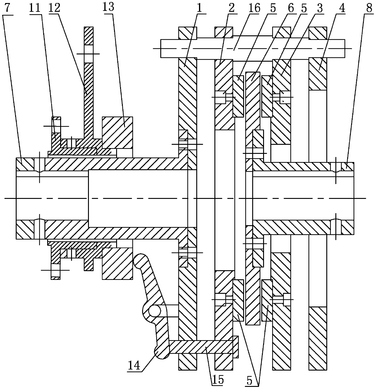
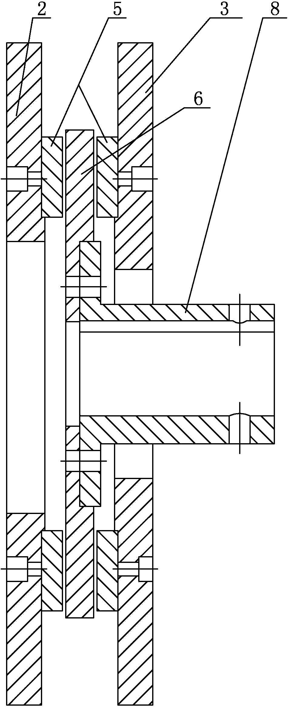
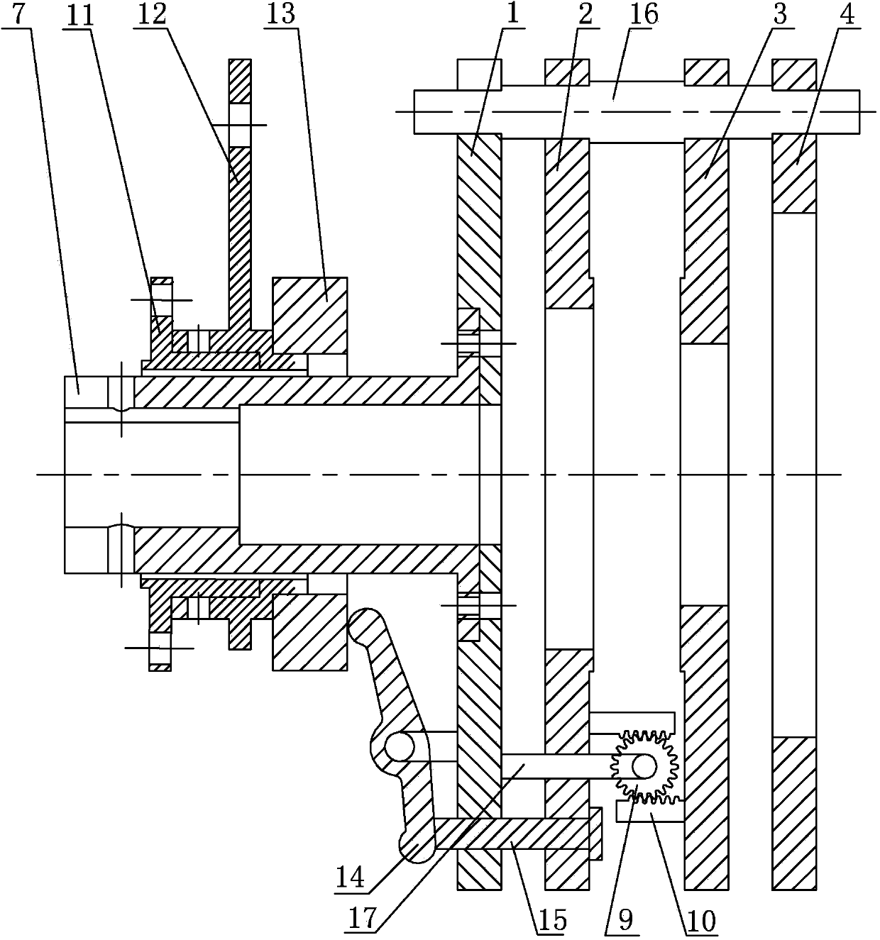
[0014] Specific implementation mode one: combine Figure 1-Figure 3 Explain that the double-sided structure speed-regulating permanent magnetic coupler of this embodiment includes a drive shaft 7, an output shaft 8, a necked flange 11, a release bearing seat 12, a release bearing 13, a first bracket 1, a second bracket 4, The first magnetically conductive active disk 2, the second magnetically conductive active disk 3, the conductive metal disk 6, at least three positioning columns 16, a plurality of permanent magnets 5 and a plurality of air gap adjustment devices;

[0015] The first bracket 1, the first magnetically conductive driving disk 2, the second magnetically conductive driving disk 3 and the second bracket 4 are arranged side by side in sequence, and the release bearing 13, the drive shaft 7 and the output shaft 8 are coaxially arranged, at least three Positioning posts 16 are evenly distributed along the circumferential direction of input shaft 7, and positioning po...

specific Embodiment approach 2

[0017] Specific implementation mode two: combination figure 1 Note that the conductive metal disc 6 in this embodiment is a copper disc. In this way, the resistivity of copper is low and the conductivity is high, which meets the requirement of permanent magnetic coupling. Others are the same as the specific implementation one.

specific Embodiment approach 3

[0018] Specific implementation mode three: combination figure 1 Note that the conductive metal disc 6 in this embodiment is an aluminum disc. With such arrangement, the resistivity of aluminum is also low and the conductivity is high, which meets the requirement of permanent magnetic coupling. Others are the same as the specific implementation one.


PUM


Abstract

The invention relates to a coupler, and discloses a double-edge structure speed regulating permanent magnet coupler for solving the problems that in an existing coal mine factory, a high-power induction motor is started in an on-load mode, due to the fact that the starting torque of the induction motor is small, when the starting torque is smaller than the load torque in value, on-load starting can not be achieved in a directly-starting mode, and an adopted controller of the motor is high in price. The double-edge structure speed regulating permanent magnet coupler comprises a driving shaft, an output shaft, a flange with a neck, a release bearing block, a release bearing, a first support, a second support, a first magnetism conducting driving disc, a second magnetism conducting driving disc, an electric conducting metal disc, at least three positioning columns, a plurality of permanent magnets and a plurality of air gap adjustment devices. The first support, the first magnetism conducting driving disc, the second magnetism conducting driving disc and the second support are sequentially arranged in parallel, and the permanent magnets are fixedly installed on the two opposite plate faces of the first magnetism conducting driving disc and the second magnetism conducting driving disc in the circumferential direction of the input shaft. The double-edge structure speed regulating permanent magnet coupler belongs to the technical field of speed regulating coupling driving.

Description

technical field [0001] The invention relates to a coupler, in particular to a double-sided permanent magnet coupler with an axial magnetic flux that can adjust the rotating speed, and belongs to the technical field of speed-regulating coupling drive. Background technique [0002] Most of the coal shearers used in coal mines use high-power induction motors. However, the starting torque of induction motors is relatively small, and it is impossible to start with load. The starting torque can only be increased by a variable voltage and frequency conversion controller. Controllers have certain limitations in special environments such as flammable, explosive, humid, and high dust content in coal mines, and high-power controllers are very expensive. [0003] The control actuators for adjusting the air gap of the speed-regulating permanent magnet coupler include manual control and signal electric control. The signal electronic control is when the speed-regulating permanent magnet c...

Claims


Application Information

Patent Timeline
IPC IPC(8): H02K51/00H02K49/10
Inventor 宋立伟孟祥瑞李书培崔总泽杨国庆崔淑梅张千帆
Owner 严格集团股份有限公司
Why Eureka
Try Eureka