compressor
A technology of a compressor and a compression mechanism, which is applied in the field of compressors, can solve the problems such as the reduction of the volume efficiency of the compressor, the reduction of the compressor efficiency, the reduction of the density, etc., and achieve the effect of suppressing the pressure loss and realizing the high efficiency.
- Summary
- Abstract
- Description
- Claims
- Application Information
AI Technical Summary
Problems solved by technology
Method used
Image
Examples
Embodiment approach 1
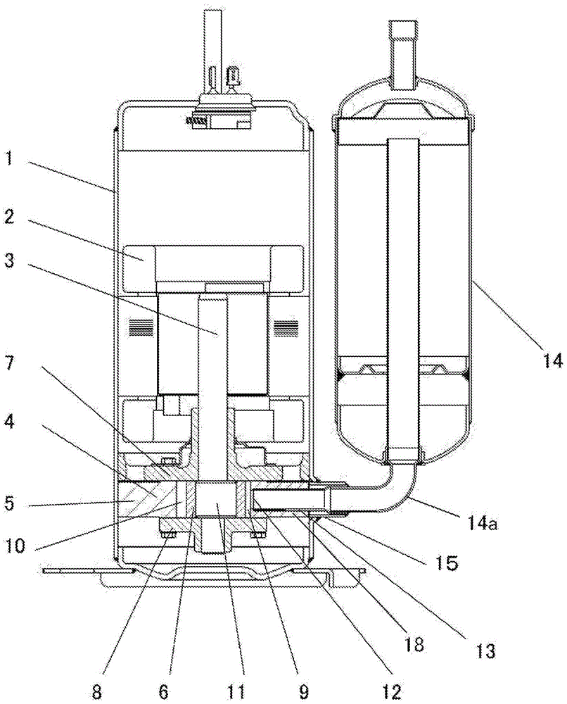
[0069] figure 1 It is a longitudinal sectional view of the compressor according to Embodiment 1 of the present invention.
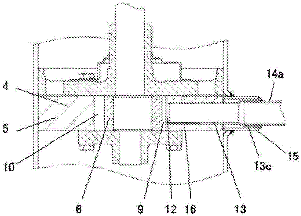
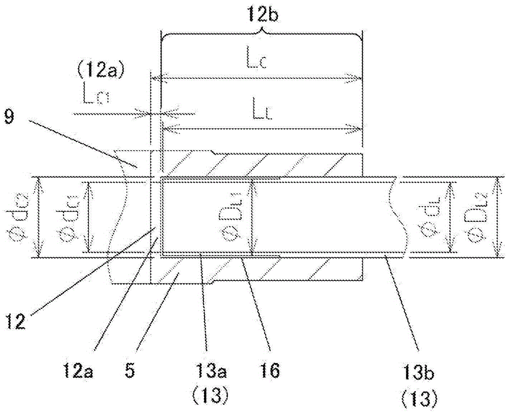
[0070] figure 1 Among them, the electric component 2 and the compression mechanism part 4 are accommodated in the airtight container 1 . The electric component 2 and the compression mechanism unit 4 are connected by a drive shaft 3 . The compression mechanism unit 4 forms a suction chamber 9 and a compression chamber 10 by partitioning the space formed by the cylinder 5 and the rotary piston 6 between the upper bearing 7 and the lower bearing 8 with vanes (not shown). A crankshaft eccentric portion 11 integrally formed with the drive shaft 3 is accommodated in the cylinder 5 , and the rotary piston 6 is rotatably attached to the crankshaft eccentric portion 11 . A vane (not shown) is slidably provided on the cylinder 5 . The vane always abuts against the rotary piston 6 , thereby partitioning the suction chamber 9 and the compression chamber 10 . A...
Embodiment approach 2
[0106] Figure 9 It is an enlarged sectional view of the vicinity of the suction hole of the compressor according to Embodiment 2 of the present invention. However, other configurations that are not shown are the same as those in Embodiment 1, and thus description thereof will be omitted.
[0107] Figure 9 Among them, the step difference between the diameter-reduced portion 12a of the suction hole 12 and the diameter-enlarged portion 12b on the upstream side is a tapered shape at an angle α. The angle α is formed by machining the enlarged diameter portion 12b of the suction hole 12 with a drill. In the case of conventional drills, the angle α is 118 degrees.
[0108] With this configuration, the same effect as that of Embodiment 1 can be obtained, of course, but in addition, since the diameter-enlarged portion 12b of the suction hole 12 can be drilled, it can contribute to improvement of workability such as shortening of work time.
[0109] Figure 10 It is an enlarged c...
Embodiment approach 3
[0112] Figure 11 It is an enlarged sectional view of the vicinity of the suction hole of the compressor according to Embodiment 3 of the present invention. However, other configurations that are not shown are the same as those in Embodiment 1, and thus description thereof will be omitted.
[0113] Such as Figure 11 As shown, the outer diameter ΦD of the large diameter portion 13b of the suction liner pipe 13 L2 Set to be slightly smaller than the inner diameter Φd of the enlarged diameter portion 12b of the suction hole 12 C2 , and the high pressure and low pressure are separated by the O-ring 17 inserted into the upstream side of the suction hole 12 . In this embodiment, the O-ring 17 constitutes a partition.
[0114] According to this structure, since the high-temperature cylinder 5 and the suction liner pipe 13 are not in direct contact, the heating of the low-temperature and low-pressure suction refrigerant gas flowing through the suction liner pipe 13 can be further s...
PUM
 Abstract
Description
Claims
Application Information
 - R&D
- Intellectual Property
- Life Sciences
- Materials
- Tech Scout
- Unparalleled Data Quality
- Higher Quality Content
- 60% Fewer Hallucinations
Browse by: Latest US Patents, China's latest patents, Technical Efficacy Thesaurus, Application Domain, Technology Topic, Popular Technical Reports.
© 2025 PatSnap. All rights reserved.Legal|Privacy policy|Modern Slavery Act Transparency Statement|Sitemap|About US| Contact US: help@patsnap.com


