CT device and CT image generation method

A technology for CT images and image slices, which is applied in the field of parallel reconstruction CT devices and CT image generation, can solve problems such as processing speed limiting bandwidth, etc., and achieve the effects of improving cache hit rate, improving access speed, and realizing combined access.

Inactive Publication Date: 2014-05-14
HITACHI LTD
View PDF5 Cites 9 Cited by
  • Summary
  • Abstract
  • Description
  • Claims
  • Application Information

AI Technical Summary

Problems solved by technology

[0011] According to the CT device involved in the present invention, by using multi-core processors such as GPU, it has high flexibility and few restrictions, and parallel computing can be realized without the GPU cluster in the prior art, which solves the problem that the processing speed in the prior art is limited by the bandwidth technical issues

Method used


Image

  • CT device and CT image generation method
  • CT device and CT image generation method
  • CT device and CT image generation method

Examples


no. 1 approach )

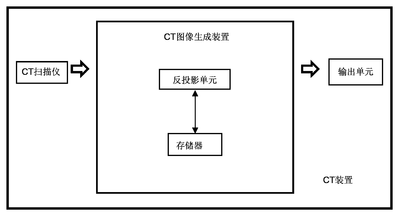
[0037] First, a first embodiment of the present invention will be described. figure 1 It is a block diagram showing a schematic configuration of a CT apparatus according to the first embodiment of the present invention. Such as figure 1 As shown, the CT apparatus of the first embodiment scans the scanning object by X-rays, outputs a three-dimensional CT image of the scanning object, and has a CT scanner, a memory, a back projection unit and an output unit. Wherein, the memory and the back projection unit constitute a CT image generating device. Each configuration of the CT apparatus will be described in detail below.

[0038] The CT scanner scans the scanned object through X-rays to obtain a projection image of the scanned object. Specifically, the radiation of a single axial plane penetrates the scanning object, and the projection image of the scanning object is obtained according to the different absorption and transmittance of X-rays for each part of the scanning object....

no. 2 approach )

[0049] Next, a second embodiment of the present invention will be described. The difference between the second embodiment and the first embodiment is that the technical idea of ​​the present invention is applied to iterative reconstruction in the field of CT image reconstruction. The following description will focus on the differences between the second embodiment and the first embodiment.

[0050] Figure 4 It is a block diagram showing a schematic configuration of a CT apparatus according to a second embodiment of the present invention. Such as Figure 4 As shown, the CT apparatus according to the second embodiment of the present invention further includes a projection unit and a comparison unit in addition to the CT apparatus according to the first embodiment. Wherein, the comparison unit, the projection unit, the memory and the back projection unit constitute the CT image generation device.

[0051] Specifically, in the CT apparatus of the second embodiment, the memory...

no. 3 approach )

[0083] Next, a third embodiment of the present invention will be described. The third embodiment is improved on the basis of the first embodiment and the second embodiment, and a specific storage method of CT image slices is provided. The following description will focus on the points of difference between the third embodiment and the first and second embodiments.

[0084] In the third embodiment of the present invention, the memory stores the predicted three-dimensional CT images in a variety of storage methods. Among the various storage methods, the directions of the planes where the CT image slices are located are different from each other; the projection unit according to the scanning direction of the CT scanner and selecting the predicted 3D CT images stored in multiple storage modes in the memory, so that the plane where the CT image slices in the predicted 3D CT images in the selected storage mode is located is closest to the vertical to the scanning direction.

[0085...


PUM


Abstract

The invention relates to a CT (Computed Tomography) device and a CT image generation method, wherein while the images of an object are processed, the data of the images are orderly stored in specified direction, and a multi-core processor is utilized to carry out back projection / projection processing of multiple threads in parallel in such a manner that each thread is orderly processed in a direction orthogonal to the specified direction, and as a result, three-dimensional CT images can be obtained and output. In this way, as the multi-core processor, for example,a GPU (Graphics Processing Unit), is utilized, the CT image generation method is high in flexibility and less in limitations, and the technical problem that the processing speed is limited by the bandwidth. In the meantime, when the multi-core processor is used for processing data in storage and back projection / projection processing, the rule of multi-threaded internal memory access of the multi-core processor, for example, the GPU, is taken into full consideration, the cache hit ratio is increased, combined access is realized and the access speed of the internal memory is greatly increased. As a result, the operational capability of the processor is sufficiently developed in CT image reconstruction and the operating speed of the CT image reconstruction is greatly increased.

Description

technical field [0001] The invention relates to a CT device and a CT image generation method, in particular to a CT device and a CT image generation method for CT image reconstruction, especially parallel reconstruction. Background technique [0002] Computed tomography (CT) is widely used in the field of medical imaging. It is a scanning method that uses computer technology to reconstruct the tomographic image of the measured object to obtain a three-dimensional tomographic image. The scanning method is to penetrate the measured object through the rays of a single axis, and according to the different absorption and transmittance of each part of the measured object, the transmitted rays are collected by the computer and imaged through three-dimensional reconstruction. [0003] Analytical reconstruction and iterative reconstruction are two basic methods of CT image reconstruction. Filtered back projection is the main algorithm of analytical reconstruction, and its reconstru...

Claims


Application Information

Patent Timeline
Patent Type & Authority Applications(China)
IPC IPC(8): A61B6/03
CPCA61B6/032A61B6/5205G06T11/006G06T2211/428
Inventor 韩颖婕盛兴东
Owner HITACHI LTD
Why Eureka
Try Eureka