Automatic filter capable of controlling slurry density and application method thereof

A slurry concentration and filter technology, which is applied in the field of solid-liquid separation and filtration devices, can solve the problems of high labor intensity of loading and unloading plates, low production efficiency, and difficulty in controlling the moisture content of the filter cake. , the effect of less auxiliary equipment and compact structure

Active Publication Date: 2014-05-14
新疆天利高新石化股份有限公司
View PDF6 Cites 3 Cited by
  • Summary
  • Abstract
  • Description
  • Claims
  • Application Information

AI Technical Summary

Problems solved by technology

[0003] The present invention provides an automatic filter capable of controlling the slurry concentration and its use method, which overcomes the deficiencies of the above-mentioned prior art, and can effectively solve the problem of high labor intensity of loading and unloading the plate and frame in the existing plate and frame filter press and the production The disadvantage of low efficiency, especially the problem that the moisture content of the filter cake is difficult to control

Method used


Image

  • Automatic filter capable of controlling slurry density and application method thereof
  • Automatic filter capable of controlling slurry density and application method thereof

Examples


Embodiment 1

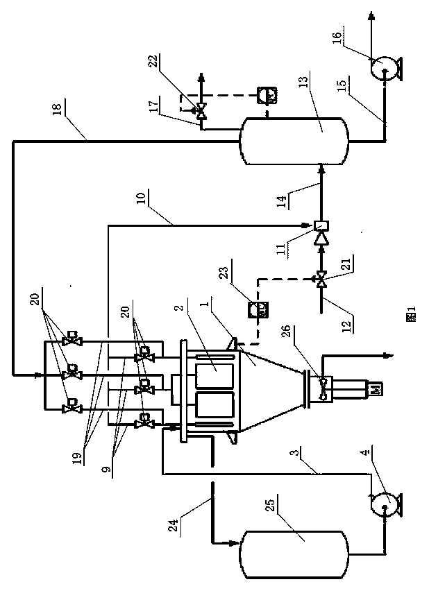
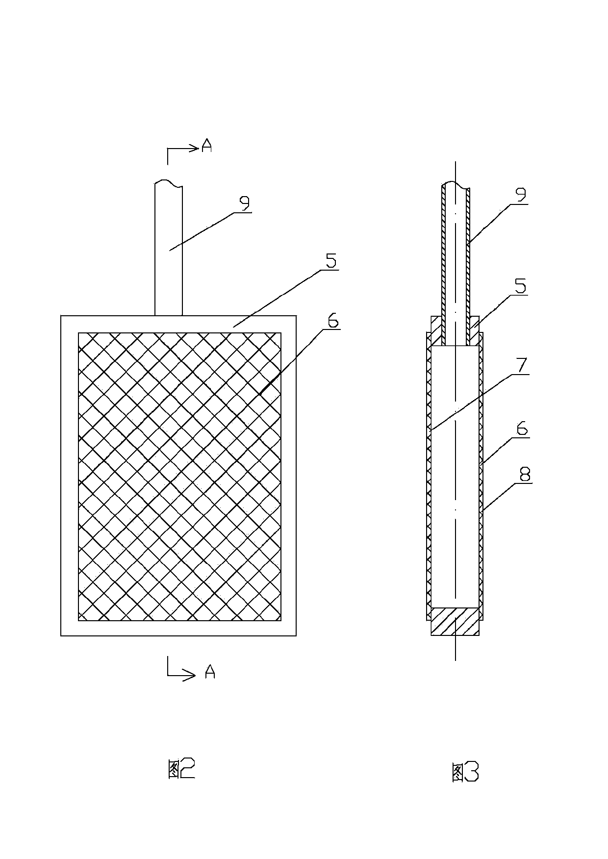
[0019] Embodiment 1, as attached figure 1 , 2 , 3, the automatic filter that can control the concentration of the slurry includes a filter tank 1, a filter rack 2, a liquid outlet main pipe 10, an air injector 11, a filtrate tank 13 and a blowback main pipe 18; the filter tank 1 The upper end of the filter tank 1 is fixedly equipped with a feed pipe 3, the feed pipe 3 is fixedly installed with a slurry pump 4, and at least three filter rackets 2 are fixedly installed in the upper inner cavity of the filter tank body 1 and are divided into three groups. Each filter racket 2 all comprises filter frame 5, front filter screen 6 and rear filter screen 7, front filter screen 6 and rear filter screen 7 are respectively sealed and fixedly installed on the front and rear sides of filter frame 5, filter frame 5, front filter screen 6 and the rear filter screen 7 jointly form a filter chamber 8, and there are installation holes on the filter frame 5 corresponding to the filter chamb...

Embodiment 2

[0021] Embodiment 2, as a preference of the above embodiment, according to needs, the number of filter beats 2 is a multiple of 3, and is divided into three groups on average. Divide the filter beat 2 into three groups on average, which can better control the timing. Among the three groups, one group is back blowing, and the other two groups are filtering. If one group or one filter beat 2 fails, it will not affect other groups. The normal work of filter beat 2 or other filter beat 2; on average, three groups work at the same time, which has a better filtering effect and makes the filter continuous.

Embodiment 3

[0022] Embodiment 3, as the preferred embodiment of the above, as attached figure 1 As shown, a clear liquid discharge pipe 24 is fixedly installed on the upper end of the filter tank body 1 . The filtered clear liquid and air are sent to the filtrate tank 13 through the air injector 11, and the excess clear liquid is discharged by the clear liquid discharge pipe 24.


PUM


Abstract

The invention relates to the technical field of solid-liquid separation filter devices and provides an automatic filter capable of controlling the slurry density and an application method thereof. The automatic filter comprises a filter tank, filter rackets, a liquid outlet main pipe, an air ejector, a filtrate tank and a back flushing main pipe, wherein a feed pipe is fixedly installed at the upper end of the filter tank; a slurry pump is fixedly installed on the feed pipe; at least three filter rackets are fixedly installed in an upper inner cavity of the filter tank; each filter racket comprises a filter frame, a front filter screen and a rear filter screen; the front and rear filter screens are hermetically and fixedly installed on the front and rear sides of the filter frame respectively. The automatic filter has a reasonable and compact structure, is convenient to apply and manufacture, can achieve unattended operation through program control in the production process, is large in filter area, can achieve continuous production, basically needs fixed parts, has little auxiliary equipment, is convenient and reliable to use, is unnecessary to be removed and installed repeatedly, thus reducing the labor intensity, effectively solving the problem that the moisture contents of filter cakes of plate-and-frame filter presses are difficult to control and being higher in production efficiency.

Description

technical field [0001] The invention relates to the technical field of solid-liquid separation and filtration devices, and relates to an automatic filter capable of controlling slurry concentration and a use method thereof. Background technique [0002] Filtration refers to the operation of using a certain porous substance as a medium, under the action of external force, to make the fluid pass through the pores of the medium and the solid particles are trapped, so as to realize the separation of solid particles and fluid. Filtration can remove particles in the gas-solid system , can also remove solid particles in the liquid-solid system. Filtration in chemical production is mostly used for solid-liquid separation in suspensions. The external force to realize the filtration operation can be gravity, pressure difference or inertial centrifugal force, but the most widely used in chemical industry is based on The pressure difference is the driving force for the filter operation....

Claims


Application Information

Patent Timeline
Patent Type & Authority Applications(China)
IPC IPC(8): B01D29/52B01D29/68B01D29/15B01D29/60B01D37/00B01D37/04
Inventor 李刚宋清山吴新祥魏建东何文宝
Owner 新疆天利高新石化股份有限公司
Why Eureka
Try Eureka