
Capper for containers

A technology for sealing machines and containers, applied in the directions of sealing machines, tightly closing containers with lids, bottle/container caps, etc. The effect of removal, efficient cleaning effect

Active Publication Date: 2014-05-14
KRONES AG
View PDF8 Cites 2 Cited by
  • Summary
  • Abstract
  • Description
  • Claims
  • Application Information

AI Technical Summary

Problems solved by technology

Therefore, cleaning these parts is correspondingly time-consuming and costly
Furthermore, such electromagnetic clutches for transmitting the necessary forces must have correspondingly large dimensions, so that the entry surface for dirt and bacteria is particularly large

Method used


Image

  • Capper for containers
  • Capper for containers

Examples


Embodiment Construction

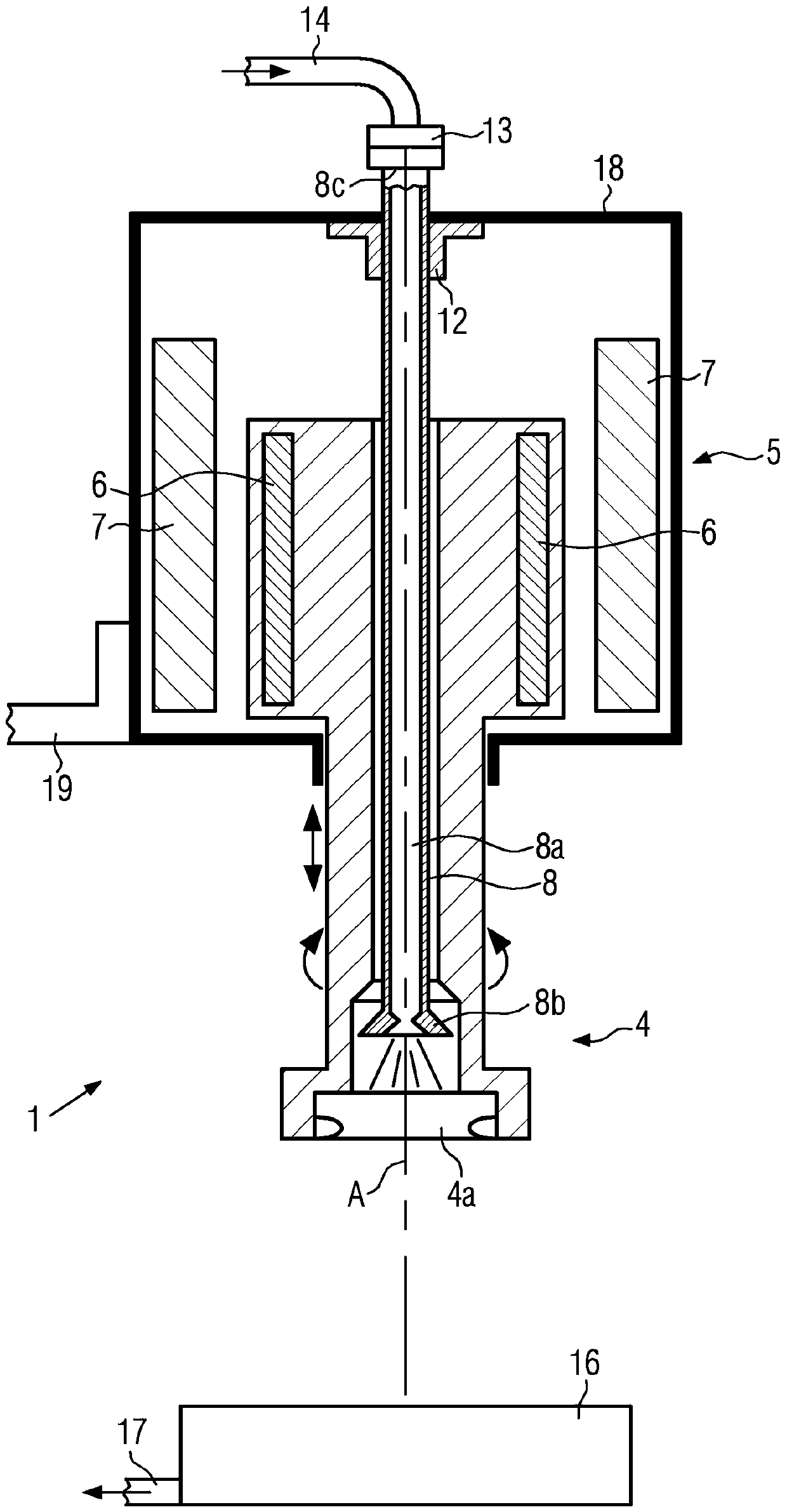
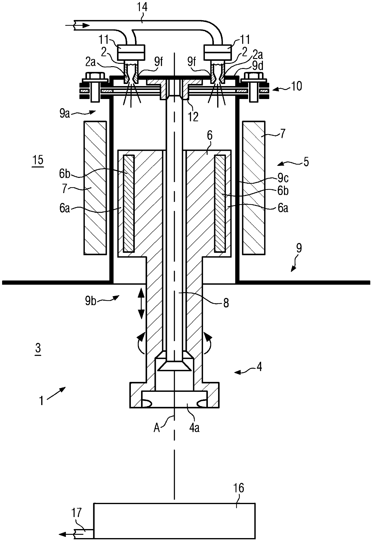
[0040] figure 1 A cross-sectional side view of the first embodiment of the sealing machine according to the present invention during cleaning is shown. The motor 5 can be seen, and its rotor 6 drives the closing head 4 in the following manner, so that the closing head can not only perform vertical lifting movements, but also rotate around the axis A. In addition, an ejector rod 8 is arranged in the closure head 4 so as to eject the container closure that is suspended in the closure head 4 or not screwed onto the container.

[0041] The stator 7 of the motor 5 generates a magnetic field, and the magnetic field acts on the magnet of the rotor 6. The stator 7 here includes a plurality of magnetic coils along the axis A and in the peripheral direction, respectively. As a result, it is possible to generate a magnetic field that can not only rotate the rotor 6 around the axis A, but also adjust the height along the axis A (according to the arrow). In the sealing machine 1, the closin...


PUM


Abstract

The present invention relates to a capper for containers. The capper comprises a capping head and an ejector bar for ejecting container closures in the capping head. The ejector bar includes at least one medium channel for a cleaning medium. The medium channel is formed as a portion of a cleaning cycle for supplying the cleaning medium into the capping head. The present invention further relates to a clean room separation device for containers for connecting the capping head with the rotor and formed between the rotor and a stator. The clean room separation device includes at least one media duct for the cleaning medium, and is used to feed the cleaning medium from ambient environment into the clean room. The present invention further relates to a filling apparatus having the capper and a method for cleaning a capper for containers, in particular bottles.

Description

Technical field [0001] The invention relates to a sealing machine which uses a closing head to close a container. Background technique [0002] The screw closure of a container (for example a bottle) can be closed in a known manner in a rotary machine with a plurality of sealing machines arranged on the periphery and rotating around a common axis, wherein the closure caps are respectively held in the closure heads And the closure cap is not only rotated but also lowered according to the screw pitch after being placed on each container mouth. Alternatively, the container can be raised accordingly during screwing on the closure cap. Here, the rotary movement of the closing head is carried out by means of an electric motor, and the lowering movement is carried out either by a control cam or a linear motor. [0003] That is to say, however, the closure cap will remain in the closure head when a container is missing, and will collide with the next closure cap in the next working cycle...

Claims


Application Information

Patent Timeline
IPC IPC(8): B67B3/00
CPCB67B3/2066B67B3/268B67B2201/08
Inventor 伯恩德·索比西
Owner KRONES AG
Learn More