
Soft soil roadbed drainage prepressing rear blocking structure and construction method

A soft soil roadbed and horizontal drainage technology, applied in infrastructure engineering, roads, roads, etc., can solve the problems of long construction period, low strength, and high engineering cost, and achieve the effect of enhancing integrity and improving bearing capacity.

Inactive Publication Date: 2014-05-14
神州建设集团有限公司
View PDF8 Cites 9 Cited by
  • Summary
  • Abstract
  • Description
  • Claims
  • Application Information

AI Technical Summary

Problems solved by technology

[0006] To sum up, although there are some methods that can be used to deal with the subsidence of the roadbed during the construction period, this method requires a long construction period, sufficient preloading and drainage consolidation time, and cannot solve the soft soil foundation itself. The post-construction settlement problem caused by the inherent secondary consolidation reasons
The composite pile foundation method is to drive a large number of various types of piles into the soft soil foundation to form a composite pile foundation to reduce the settlement of the foundation. The cost of this method is very high, which is more than ten times or even several times that of the drainage consolidation method. More than ten times, can not be used in large quantities in actual engineering
Especially when the strength of the foundation soil is low, a lot of piles need to be drilled, and the project cost is very expensive

Method used


Image

  • Soft soil roadbed drainage prepressing rear blocking structure and construction method
  • Soft soil roadbed drainage prepressing rear blocking structure and construction method
  • Soft soil roadbed drainage prepressing rear blocking structure and construction method

Examples


Embodiment Construction

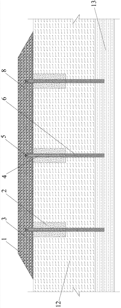
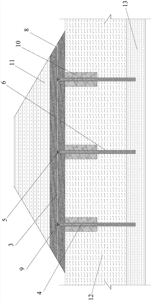
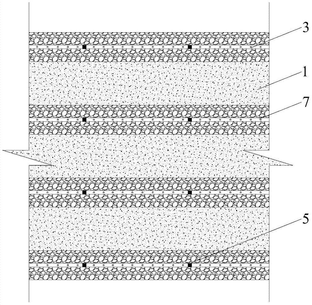
[0032] In this embodiment, the design and construction technical requirements of the embankment and pavement structure, the construction technical requirements of the horizontal drainage cushion, the vertical drainage body horizontal grouting pipe, and the vertical grouting pipe will not be repeated in this embodiment, and the emphasis will be on The invention relates to embodiments of structures.

[0033] figure 1 It is a cross-sectional view of the soft soil subgrade drainage preloading period structure of the present invention, figure 2 It is a cross-sectional view of the structure in the plugging period after drainage of the soft soil subgrade of the present invention, image 3 It is a horizontal sectional view of the plugging structure after drainage and preloading of the soft soil roadbed of the present invention. refer to figure 1 , figure 2 , image 3 As shown, the road to be reinforced is a two-way six-lane first-class road, and the cross section after the dr...


PUM


Abstract

The invention relates to a soft soil roadbed drainage prepressing rear blocking structure. The structure is characterized in that discrete material short piles, plastic drainage plates, a horizontal drainage pad layer, vertical grouting pipes and a horizontal grouting pipe are structurally included, the discrete material short piles are arranged below the horizontal drainage pad layer, the vertical grouting pipes and the plastic drainage plates are arranged in the discrete material short piles, the horizontal drainage pad layer is laid below roadbed filler, the horizontal grouting pipe is laid in the horizontal drainage pad layer, the horizontal grouting pipe and the vertical grouting pipes are communicated through tee joints, after roadbed drainage prepressing is finished, grout is injected into the discrete material short piles and the horizontal drainage pad layer through the vertical grouting pipes and the horizontal grouting pipe to form vertical grouting sealed short piles and a grouting solidified pad layer bearing plate. According to the structure, performance of readbed soil is improved through drainage consolidation of the roadbed soil, the problem that pre-construction settlement of a road segment processed in a drainage consolidation method is exceedingly large can be solved, and meanwhile, bearing capacity and integrity of the roadbed can be improved through grout injection. The invention further discloses a construction method of the preceding structure.

Description

Technical field [0001] The present invention involves a kind of fluxing structure and construction method after the pre -pressure pre -pressure of the soft soil base drainage. It belongs to the foundation of the foundation engineering and is suitable for the foundation processing engineering of road engineering with high thickness and high sedimentation control requirements. Background technique [0002] Softland is widely distributed in my country, and soft soil covers deep -covered areas in the middle and lower reaches of the coast and river.In the construction of the road, we often encounter the situation of crossing farmland, river or soil, and more groundwater, which is the so -called soft soil foundation.The soft soil has the characteristics of large water content, low shear strength, and poor overload capacity.If it is not handled or processed properly, the ground base will be stable, which will not only cause engineering problems such as road structure destruction and bri...

Claims


Application Information

Patent Timeline
IPC IPC(8): E02D3/10E01C3/04
Inventor 徐辞剑田向东叶国江薛玉明
Owner 神州建设集团有限公司
Learn More