Solar house system suitable for severe cold area

A solar house and area technology, applied in the field of solar house systems, can solve problems affecting indoor thermal comfort, no fresh air in the room, overheating of the solar house, etc., and achieve the effect of alleviating instability, alleviating overheating in summer, and increasing the heat dissipation area

Inactive Publication Date: 2014-05-14
HARBIN INST OF TECH
View PDF4 Cites 1 Cited by
  • Summary
  • Abstract
  • Description
  • Claims
  • Application Information

AI Technical Summary

Problems solved by technology

[0005] The present invention aims to solve the problems that the existing solar houses in villages and towns in severe cold areas have low indoor heating temperature in winter, no fresh air in the room, poor air quality, and the solar houses are overheated due to solar radiation in summer and affect indoor thermal comfort, and further provide A solar room system suitable for severe cold regions

Method used


Image

  • Solar house system suitable for severe cold area
  • Solar house system suitable for severe cold area

Examples


specific Embodiment approach 1

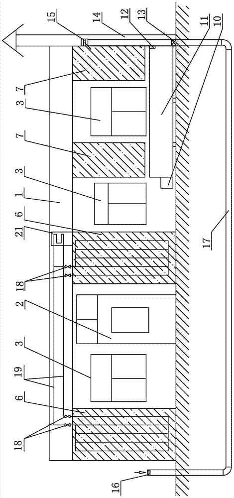
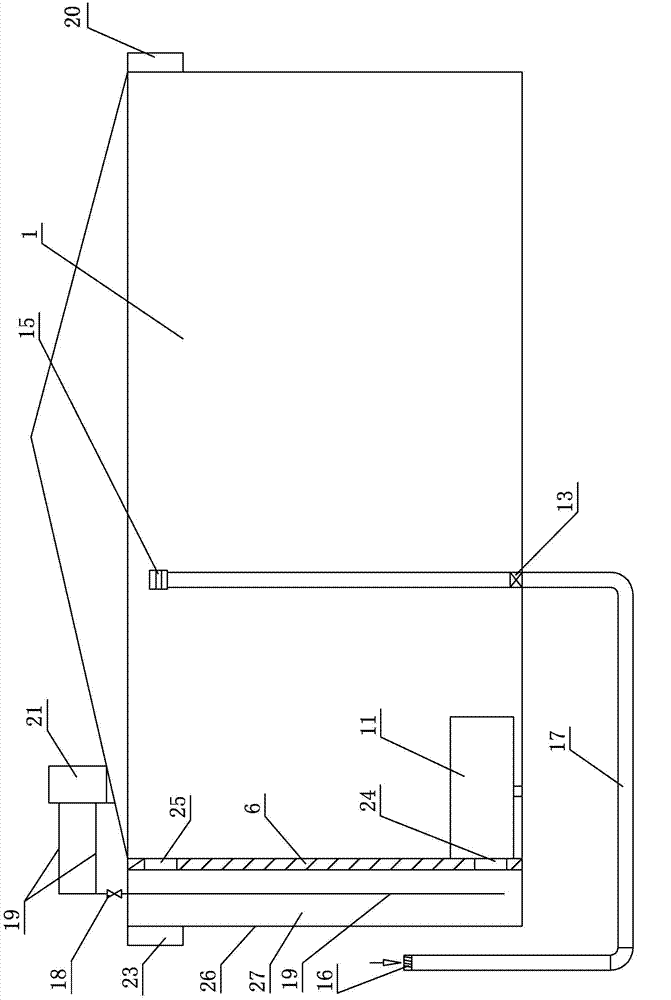
[0014] Specific implementation mode one: combine Figure 1-Figure 2 Explain that the solar house system suitable for severe cold areas in this embodiment includes a passive solar house 1, a suspension 11, a fresh air fan 13, a smoke exhaust channel 14, a buried pipe 17, a shut-off valve 18, a refrigerant circulation pipe 19 and a heat preservation water tank 21 ; Three direct benefit windows 3 are installed on the passive solar house 1, two first solar heat collecting walls 6 and two second solar heat collecting walls 7 are arranged on the passive solar house 1, two first solar heat collecting walls There are air heat channels 27 in the walls 6, and a smoke exhaust channel 14 is arranged on the outer wall of the passive solar house 1. A hanging kang 11 is installed in the passive solar house 1, and the hanging kang 11 communicates with the smoke exhaust channel 14. One end of 17 protrudes from the ground, and the other end of the underground pipe 17 is inserted into the smoke ...

specific Embodiment approach 2

[0016] Specific implementation mode two: combination Figure 1-Figure 2 Note that the refrigerant coil 19 in this embodiment is a copper tube. With such setting, it is strong, strong in corrosion resistance, easy to deform, strong in temperature adaptability, and easy to install and use. Others are the same as in the first embodiment.

specific Embodiment approach 3

[0017] Embodiment 3: The refrigerant in the refrigerant circulation pipe 19 of this embodiment is any one of difluorochloromethane, difluorodichloromethane and R410A refrigerant. With such setting, the refrigeration effect is good, safe and reliable, and easy to use. Others are the same as in the first or second embodiment.


PUM


Abstract

The invention relates to a solar house system, in particular to a solar house system suitable for the severe cold area. The solar house system aims at solving the problems that as for an existing town solar house in the severe cold area, the heating temperature of an indoor heated brick bed is low in winter, fresh air does not exist indoors, the air quality is poor, and due to solar radiation, the solar house is overheated in summer, and the indoor heat comfort is influenced. The solar house system comprises a passive solar house, a hung brick bed, a fresh air fan, a smoke discharging channel, a buried pipe, stop valves, refrigerant circulating pipes and a heat preservation water tank. Three direct benefiting windows are installed in the passive solar house, two first solar heat collecting walls and two second solar heat collecting walls are arranged on the passive solar house, the hung brick bed is installed in the passive solar house, one end of the buried pipe extends out of the ground, the other end of the buried pipe is inserted into the smoke discharging channel and extends into the solar house, the fresh air fan is installed at the position, located at the ground, of the buried pipe, the refrigerant circulating pipes are arranged in an air heat channel and the heat preservation water tank, and the stop valves are installed on the refrigerant circulating pipes. The solar house system is used for the town solar house in the severe cold area.

Description

technical field [0001] The invention relates to a solar house system, in particular to a village and town solar house system suitable for severe cold regions. Background technique [0002] In villages and towns in severe cold areas, kangs are still used for heating in winter. However, kang houses in northern rural areas generally have problems such as poor heating of kangs, smoke falling, low thermal efficiency, low indoor temperature, and serious indoor air pollution. The reason is that the combustion consumes a large amount of oxygen in the room, and the smoke exhaust is not smooth, which pollutes the indoor air. Moreover, the existing building envelope has good thermal insulation and airtight performance, and very little fresh air penetrates into the room through the doors, windows and envelope. However, the fresh air system is not considered at all in rural buildings. Especially in the heating season, the indoor air quality of kang-burning villages and towns is extremely...

Claims


Application Information

Patent Timeline
Patent Type & Authority Applications(China)
IPC IPC(8): E04H1/02E04B1/74F25B29/00
Inventor 姜益强陈龙董建锴
Owner HARBIN INST OF TECH
Why Eureka
Try Eureka