Electronic beam axial velocity measurement system

An axial velocity and measurement system technology, applied in the field of vacuum electronics, can solve the problems of inaccurate electronic current injection measurement, aggravated electric field distortion, lead bombardment, etc., achieve good anti-space electromagnetic wave interference ability, improve measurement accuracy, reduce electric field Distortion effect

Inactive Publication Date: 2014-05-14
INST OF ELECTRONICS CHINESE ACAD OF SCI
View PDF3 Cites 4 Cited by
  • Summary
  • Abstract
  • Description
  • Claims
  • Application Information

AI Technical Summary

Problems solved by technology

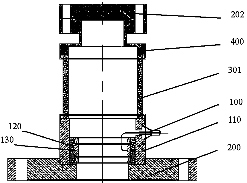
[0007] (1) The bombardment of the electron beam produces a large number of secondary electrons on the flat blind flange, which makes the measurement of the electron beam current inaccurate, and the secondary electron bombardment on the inner electrode of the capacitance probe will interfere with the induced voltage of the electron beam Measurement;
[0008] (2) When the electron beam with a large lateral velocity passes through the capacitance probe, part of the edge electrons diverge and hit the inner electrode of the probe, which makes the induced voltage of the electron beam transmitted by the inner electrode wrong, and even has the risk of destroying the inner electrode;
[0009] (3) Since the electronic injection induction ring and the insulating ceramic have a certain thickness, there is a large non-radial electric field at the front and rear edges of the induction ring, which increases the distortion of the voltage waveform measured on the electronic injection induction ring, making the detection The results and subsequent calculations all bring large errors;
[0010] (4) Since the lead wires of the electron injection induction loop are drawn separately from the rear edge, this aggravates the electric field distortion, and the lead wires are easily bombarded by stray electrons, which reduces the accuracy of probe detection

Method used


Image

  • Electronic beam axial velocity measurement system
  • Electronic beam axial velocity measurement system
  • Electronic beam axial velocity measurement system

Examples


Embodiment Construction

[0043] In order to make the objectives, technical solutions, and advantages of the present invention clearer, the following further describes the present invention in detail in conjunction with specific embodiments and with reference to the accompanying drawings. It should be noted that in the drawings or description of the specification, similar or identical parts use the same drawing numbers. The implementations not shown or described in the drawings are those known to those of ordinary skill in the art. In addition, although this article may provide an example of a parameter containing a specific value, it should be understood that the parameter does not need to be exactly equal to the corresponding value, but can be approximated to the corresponding value within acceptable error tolerances or design constraints. The directional terms mentioned in the embodiments, such as "upper", "lower", "front", "rear", "left", "right", etc., are only directions with reference to the draw...


PUM


Abstract

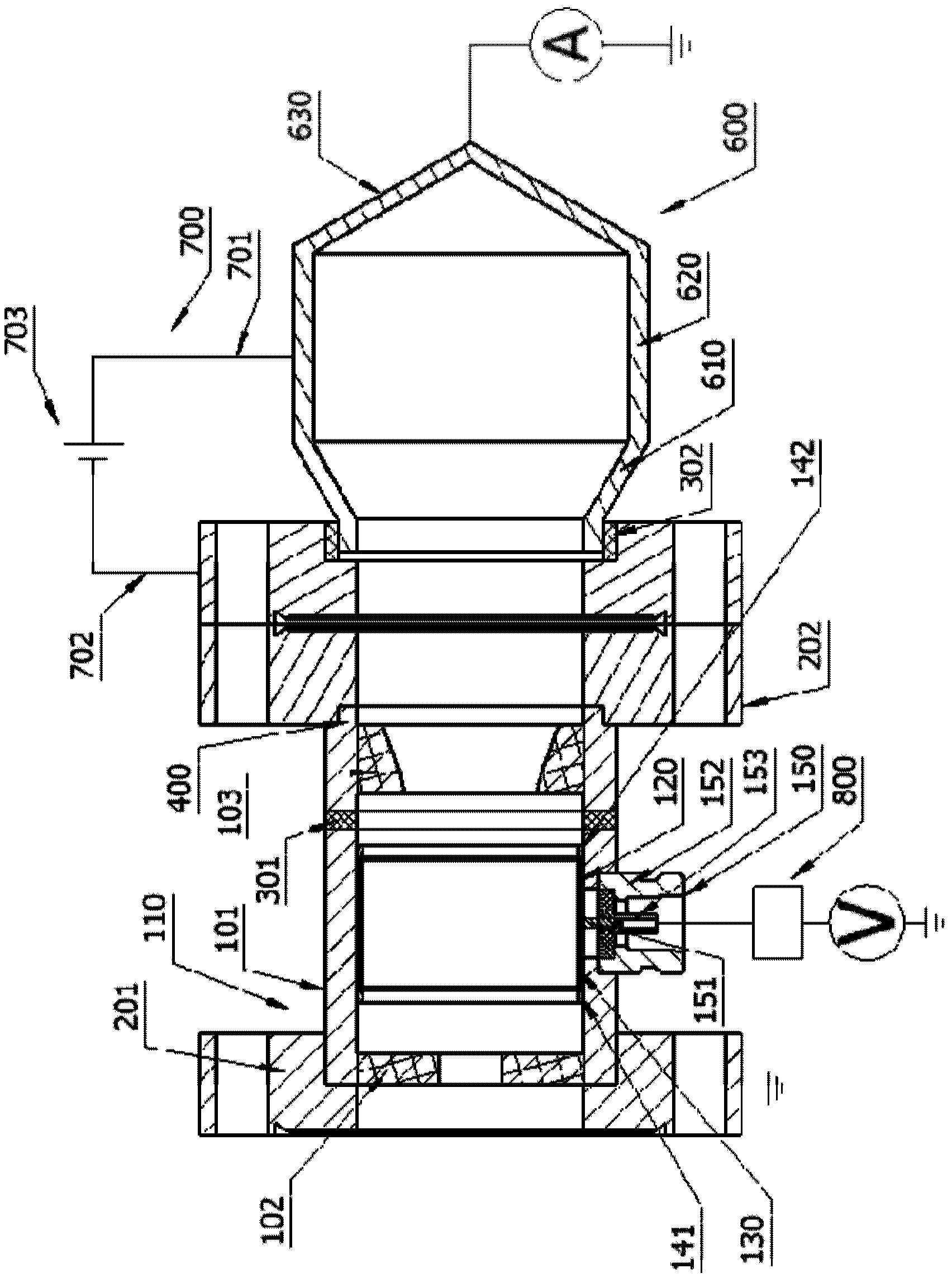
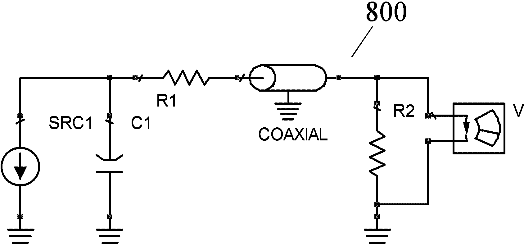
The invention provides an electron beam axial velocity measurement system which comprises a capacitive probe device, a collector cavity structure, a voltage integral and transmission circuit, a voltage measurement device and a current measurement device. The capacitive probe device comprises a main cavity structure and an electron beam induction ring; the collector cavity structure is communicated with the main cavity structure and is in a shape of a spindle with a large middle and two small ends; the front end of the voltage integral and transmission circuit is electrically connected to the electron beam induction ring and used for converting inductive charge generated when electron beams penetrate through a capacitive probe into voltage signals; the voltage measurement device is electrically connected to the rear end of the a voltage integral and transmission circuit; the current measurement device is electrically connected to the collector cavity structure. By means of the electron beam axial velocity measurement system, influence of stray electrons during measurement is reduced, and measurement precision of electron beam axial velocity is increased.

Description

Technical field [0001] The invention relates to the technical field of vacuum electronics, in particular to an electronic beam axial velocity measurement system. Background technique [0002] Electric vacuum device is a kind of active electronic device that uses the interaction of electron beam and high-frequency electromagnetic field to realize the function of microwave power amplification and conversion in vacuum or gas medium. Nowadays, electric vacuum devices have been widely used in the fields of radar, electronic countermeasures, guidance and satellite communications. With the development of electric vacuum device technology, various electronic beam measurement systems have emerged. The axial velocity of the electron beam is an important property of the electron beam. [0003] figure 1 It is a structural schematic diagram of the measurement system in the prior art electronic beam axis velocity measurement system. Such as figure 1 As shown, the front end of the capacitive p...

Claims


Application Information

Patent Timeline
Patent Type & Authority Applications(China)
IPC IPC(8): H01J37/244
Inventor 阮存军李庆生李崇山姜波李彦峰
Owner INST OF ELECTRONICS CHINESE ACAD OF SCI
Why Eureka
Try Eureka