
Small photo-thermal combination solar power station

A solar energy and photothermal technology, applied in the field of solar energy application, can solve the problems of not being able to reduce the temperature of the components well, it is difficult to obtain economic benefits, and the heat collection is scattered, and achieves the effect of being beneficial to the collection and utilization, the structure is simple, and the heat loss is reduced.

Inactive Publication Date: 2014-05-14
江苏万丰光伏有限公司
View PDF5 Cites 1 Cited by
  • Summary
  • Abstract
  • Description
  • Claims
  • Application Information

AI Technical Summary

Problems solved by technology

[0002] At present, in the domestic solar photovoltaic industry, there are also attempts to use solar photovoltaic modules to design combined photothermal devices or power stations, but most of them collect the heat generated by the modules in the form of "collector tubes", which leads to scattered heat collection and low efficiency. , nor can it reduce the temperature of the components during normal operation, and it is difficult to obtain good economic benefits

Method used


Image

  • Small photo-thermal combination solar power station

Examples


Embodiment 1

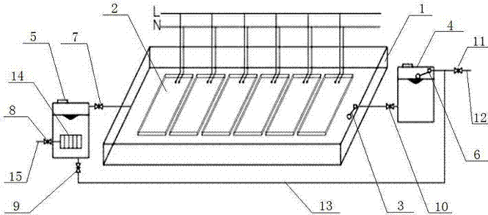
[0024] This embodiment provides a small solar power station with integrated light and heat, the structure of which is as follows: figure 1 As shown, it includes a shallow water tank 1 and a solar solar power generation assembly 2, and the shallow water tank 1 is made of heat insulating material. The bottom of one side of the shallow water tank 1 is centered with a water outlet, and the other side of the shallow water tank 1 is provided with a first ball float valve 3, which is connected to the cold water tank 4 and controls the water level of the shallow water tank 1.

[0025] The number of solar power generation components 2 is 5-30 pieces. The solar power generation components 2 are filling junction box components. The solar power generation components 2 are arranged in parallel and fixed inside the shallow water tank 1. The upper surface of the upper surface is not immersed in water, and each solar power generation module 2 is connected in parallel and then connected to the...

Embodiment 2

[0031] This embodiment is similar to Embodiment 1, the difference lies in the connection mode of the solar power generation components 2, the solar power generation components 2 in this embodiment are connected in series, and the number of solar power generation components 2 is 5-30 pieces.

[0032] The working mode of this embodiment is the same as that of Embodiment 1.


PUM


Abstract

The invention discloses a small photo-thermal combination solar power station. The small photo-thermal combination solar power station comprises a shallow water channel and solar power generation components, wherein the solar power generation components are arranged in the shallow water channel in an array mode, water is poured into the shallow water channel, it is guaranteed that the upper surfaces of the solar power generation components are not soaked in water, all the solar power generation components are connected with an inverter and a load in sequence after being connected in parallel or in series to form a distributed solar power station, the inverter and the load are arranged outside the shallow water channel, a water outlet is formed in the bottom of one side edge of the shallow water channel, a first ball float valve is arranged on the other side edge of the shallow water channel and connected with a cold water tank and controls the water level of the shallow water channel, a second ball float valve is arranged in the cold water tank, the cold water tank is connected with a cold water circulating mechanism and a water inlet pipe through the second float ball valve, and the other end of the cold water circulating mechanism is connected with the water outlet through a first stop valve. The small photo-thermal combination solar power station is simple in structural design, low in cost, good in cooling performance, high in power generation efficiency, and capable of sufficiently collecting and utilizing heat emitted by the solar power generation components.

Description

technical field [0001] The invention relates to a solar power station, in particular to a small-scale photothermal combined solar power station, which belongs to the technical field of solar energy applications. Background technique [0002] At present, in the domestic solar photovoltaic industry, there are also attempts to use solar photovoltaic modules to design combined photothermal devices or power stations, but most of them collect the heat generated by the modules in the form of "collector tubes", which leads to scattered heat collection and low efficiency. , and cannot well reduce the temperature of the components during normal operation, and it is difficult to obtain good economic benefits. Contents of the invention [0003] The technical problem to be solved by the present invention is to overcome the disadvantages of the prior art and provide a small solar thermal power station with simple structure, low cost, good heat dissipation and high power generation effic...

Claims


Application Information

Patent Timeline
IPC IPC(8): H02S10/30
CPCY02E10/50
Inventor 赵庆生吴宝安
Owner 江苏万丰光伏有限公司
Learn More