Supercharge Your Innovation With Domain-Expert AI Agents!

Drill string element with fluid activation zone

A drill string and activation area technology, applied in the field of oil and gas reservoir exploration and development, can solve the problems of small rigidity, achieve good lifting capacity, reduce the risk of clogging, and increase the effect of transmission capacity

Active Publication Date: 2019-08-13
VALLOUREC DRILLING PROD FRANCE
View PDF10 Cites 0 Cited by
  • Summary
  • Abstract
  • Description
  • Claims
  • Application Information

AI Technical Summary

Problems solved by technology

However, there is a need to reduce drill string weight and concomitant less rigidity, while maintaining or even improving the drilling fluid and the rise of cuttings generated while drilling

Method used


Image

  • Drill string element with fluid activation zone
  • Drill string element with fluid activation zone
  • Drill string element with fluid activation zone

Examples


Embodiment Construction

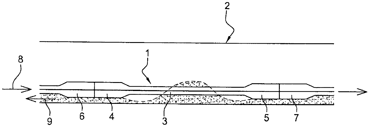
[0043] figure 1 A portion of a drill string 1 in an almost horizontal portion 2 of a formation well is shown. The drill string 1 is shown in part by a hollow tubular element 3 comprising two joints 4 and 5, by which each end of the element 3 is connected to complementary tubular elements 6 and 7 of the drill string. The drill string 1 defines a continuous central space for the flow of drilling fluid as indicated by arrows 8 . A drilling tool such as a drill bit works at the bottom of the borehole, then drilling fluid or drilling mud rises in the annular space between the borehole wall and the outer surface of the drill string 1 , see arrow 9 .

[0044] As the drilling fluid rises over the drill pipe, it carries debris from the formation traversed by the drilling tool to the surface from which the well is being drilled. The operation of the drill pipe according to the prior art is shown in figure 1 . exist figure 1 It was observed that debris carried by the drilling fluid ...


PUM


Abstract

A tubular drill pipe string element (3) comprising a substantially cylindrical body (12) and two joints (4, 5), each joint being arranged at one end of the cylindrical body and provided with a complementary element capable of A threaded portion (18, 19) of the connection, at least one of the two joints has a lifting surface (22) capable of cooperating with a lifting tool of the tubular drill string element for assembly of the tubular drill string element in the drill string , characterized in that the lifting surface has a non-circular cross-section forming an activation zone (24) for drilling fluid.

Description

technical field [0001] The invention relates to the field of exploration and development of oil and gas reservoirs, in which a rotating drill string is used. A drill string may include drill pipe, heavy mud drill pipe, drill collars, stabilizers and subs. Drill pipes are assembled by screwing one after the other into a sucker rod string, which constitutes a large or even major part of the length of the drill string. The present invention more particularly relates to profiles for rotary drilling equipment, such as drill pipe in a sucker rod string for rotary drilling. Background technique [0002] The characteristics of the drill string and more broadly the drill string elements are responsible for the quality, performance and safety of the entire drilling process, either during the drilling phase itself or during the implementation phase between downhole and surface. [0003] The development of oil and gas exploration requires the formation of more and more complex traject...

Claims


Application Information

Patent Timeline
Patent Type & Authority Patents(China)
IPC IPC(8): E21B17/10E21B17/22
CPCE21B17/10E21B17/22E21B17/1078E21B37/00E21B17/006E21B17/042
Inventor C·罗阿尔T·迪德里
Owner VALLOUREC DRILLING PROD FRANCE
Features
  • R&D
  • Intellectual Property
  • Life Sciences
  • Materials
  • Tech Scout
  • Unparalleled Data Quality
  • Higher Quality Content
  • 60% Fewer Hallucinations
Learn More